00193365-0202.pdf - 第17页
Retrofit instructions Splice sensors 8 - 72 mm 07/2003 Edition 17 3 S plice sensors for 2x8 mm and 3x8mm feeders This doc ument describ es how to retr ofit the 2x8 mm and 3x8 mm feeder or the 12/16, 24/32, 44, 56 and 72 …
Nachrüstanleitung Spleisssensoren 8 - 72 mm
Ausgabe 07/2003
16
Installation der Spleissstellenerkennung auf dem Förderer 2
: Montieren Sie die Feder der Spleisstellenerkennung mit den 2 M3 x 4 Schrauben an den
Haltewinkel.
: Schieben Sie den Haltewinkel zurück in den Förderer, bis die Nut in die Stifte innerhalb des
Förderers einrastet, wo sie vorher eingerastet war.
Befestigen Sie den Haltewinkel auf beiden Seiten des Förderers mit den Kreuzschlitzschrau-
ben. Der Spleisssensor ist jetzt montiert.
Installation des Förderers 2
: Stellen Sie den fertig montierten Förderer auf den BE-Tisch in der Maschine.
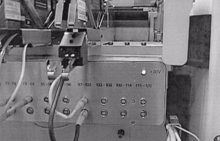
: Schließen Sie das Kommunikationskabel des Förderers und das des Spleisssensors an wie
im Bild unten, Abb. 2 - 6, gezeigt.
2
Abb. 2 - 6 Installierte Kommunikations-Kabel
Die Installation ist komplett. Weitere Informationen erhalten Sie in der Betriebsanleitung des
Spleisssensors. 2
LEDs an Spleisssensoren 2
Die LEDs an den Spleisssensoren haben folgende Aussagen: 2
– LED an: betriebsbereit
– LED aus: bei Durchlauf einer Spleissstelle.
2
Retrofit instructions Splice sensors 8 - 72 mm
07/2003 Edition
17
3 Splice sensors for 2x8mm and 3x8mm feeders
This document describes how to retrofit the 2x8 mm and 3x8 mm feeder or the 12/16, 24/32, 44,
56 and 72 mm feeder with a sensor for detecting splices. 3
3.1 Important notes
– If you have to return the feeder because of a defect, you must first remove the splice sensor.
If you return a feeder to the vendor with the splice sensor still attached, there is no way to guar-
antee that the sensor will be returned with the replacement feeder.
– Please note that the splice sensor is not suitable for tape material that contains metal. Splices
must be created using standard SIPLACE equipment (splicing tool) and must consist of metal.
– Please also note that splices must be created so that the brass strip is beneath the tape.
3.2 Tools
You will need the following tools for installation: 3
– Phillips screwdrivers
– 2.5 mm hexagon screwdriver
3.3 Parts list
Qty Designation Part no.:
-1
Splice Detection Sensor 2x8 mm 00141205-01
-
(including 2 screws M3 * 25mm )
-1
Splice Detection Sensor 3x8 mm 00141206-01
-
(including 2 screws M3 * 25mm )
-1
Splice Detection Sensor 12/16 mm 00141207-01
-
(including 2 screws M3 * 25mm )
-1
Splice Detection Sensor 24/32 mm 00141208-01
-
(including 2 screws M3 * 25mm )
-1
Splice Detection Sensor 44 mm 00141209-01
-
(including 2 screws M3 * 25mm )
-1
Splice Detection Sensor 56 mm 00141211-01
-
(including 2 screws M3 * 25mm )
-1
Splice Detection Sensor 72 mm 00141212-01
-
(including 2 screws M3 * 25mm )

Retrofit instructions Splice sensors 8 - 72 mm
07/2003 Edition
18
3.4 Safety instructions
3
DANGER
The splice sensor retrofit, including all the work described below, must only be carried out by
SIPLACE service engineers. 3
The safety instructions from the “Operational safety” chapter of the user manual and the service
manual take precedence over these instructions. 3
The placement machines are supplied with 3 x 400 VAC ± 10 %, 50/60 Hz main power voltage.3
Consequently parts of these systems inside the machine frame carry dangerous voltages, even
when switched off at the main switch. 3
Always follow the accident prevention regulations, DIN or other standards and special safety rules
applicable in your country. Always follow DIN EN 60204 and DIN VDE 105-100 when working in-
side the machine tool table. 3
Pay attention to the information concerning residual voltages in the Operational Safety chapter.3
Remember to follow the ESD regulations (see chapter Operational safety). 3
3
3
: Remove the feeder from the component table and detach the connecting cable before starting
work.
3
3
3
3
3
3
3
3
3
3
3