00193365-0202.pdf - 第18页
Retrofit instructions Splice s ensors 8 - 72 m m 07/2003 Edition 18 3.4 Saf ety instructions 3 DANGER The spl ice sensor ret rofit, in cluding all the work desc ribed belo w , must on ly be carri ed out by SIPLACE servic…
Retrofit instructions Splice sensors 8 - 72 mm
07/2003 Edition
17
3 Splice sensors for 2x8mm and 3x8mm feeders
This document describes how to retrofit the 2x8 mm and 3x8 mm feeder or the 12/16, 24/32, 44,
56 and 72 mm feeder with a sensor for detecting splices. 3
3.1 Important notes
– If you have to return the feeder because of a defect, you must first remove the splice sensor.
If you return a feeder to the vendor with the splice sensor still attached, there is no way to guar-
antee that the sensor will be returned with the replacement feeder.
– Please note that the splice sensor is not suitable for tape material that contains metal. Splices
must be created using standard SIPLACE equipment (splicing tool) and must consist of metal.
– Please also note that splices must be created so that the brass strip is beneath the tape.
3.2 Tools
You will need the following tools for installation: 3
– Phillips screwdrivers
– 2.5 mm hexagon screwdriver
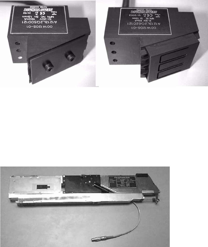
3.3 Parts list
Qty Designation Part no.:
-1
Splice Detection Sensor 2x8 mm 00141205-01
-
(including 2 screws M3 * 25mm )
-1
Splice Detection Sensor 3x8 mm 00141206-01
-
(including 2 screws M3 * 25mm )
-1
Splice Detection Sensor 12/16 mm 00141207-01
-
(including 2 screws M3 * 25mm )
-1
Splice Detection Sensor 24/32 mm 00141208-01
-
(including 2 screws M3 * 25mm )
-1
Splice Detection Sensor 44 mm 00141209-01
-
(including 2 screws M3 * 25mm )
-1
Splice Detection Sensor 56 mm 00141211-01
-
(including 2 screws M3 * 25mm )
-1
Splice Detection Sensor 72 mm 00141212-01
-
(including 2 screws M3 * 25mm )

Retrofit instructions Splice sensors 8 - 72 mm
07/2003 Edition
18
3.4 Safety instructions
3
DANGER
The splice sensor retrofit, including all the work described below, must only be carried out by
SIPLACE service engineers. 3
The safety instructions from the “Operational safety” chapter of the user manual and the service
manual take precedence over these instructions. 3
The placement machines are supplied with 3 x 400 VAC ± 10 %, 50/60 Hz main power voltage.3
Consequently parts of these systems inside the machine frame carry dangerous voltages, even
when switched off at the main switch. 3
Always follow the accident prevention regulations, DIN or other standards and special safety rules
applicable in your country. Always follow DIN EN 60204 and DIN VDE 105-100 when working in-
side the machine tool table. 3
Pay attention to the information concerning residual voltages in the Operational Safety chapter.3
Remember to follow the ESD regulations (see chapter Operational safety). 3
3
3
: Remove the feeder from the component table and detach the connecting cable before starting
work.
3
3
3
3
3
3
3
3
3
3
3
Retrofit instructions Splice sensors 8 - 72 mm
07/2003 Edition
19
3.5 Preparatory work
: Read the retrofit instructions and familiarize yourself with the splice sensor for 2x8 mm or 3x8
mm feeders.
3
Fig. 3 - 1 Splice sensors for 8 mm feeders
3.6 Installation
: Open the protective cover.
: Remove the 2x8 mm or 3x8 mm feeder from the machine.
3
Fig. 3 - 2 2x8 mm feeder
3
Splice sensor 2x8 mm
Splice sensor 3x8 mm