00193365-0202.pdf - 第20页
Retrofit instructions Splice s ensors 8 - 72 m m 07/2003 Edition 20 : Remove the tape guide pl ate from the feede r . 3 Fig. 3 - 3 Unscrewing the tape guide plate 3 : Fix the tape gui de plate to th e sensor bloc k using…
Retrofit instructions Splice sensors 8 - 72 mm
07/2003 Edition
19
3.5 Preparatory work
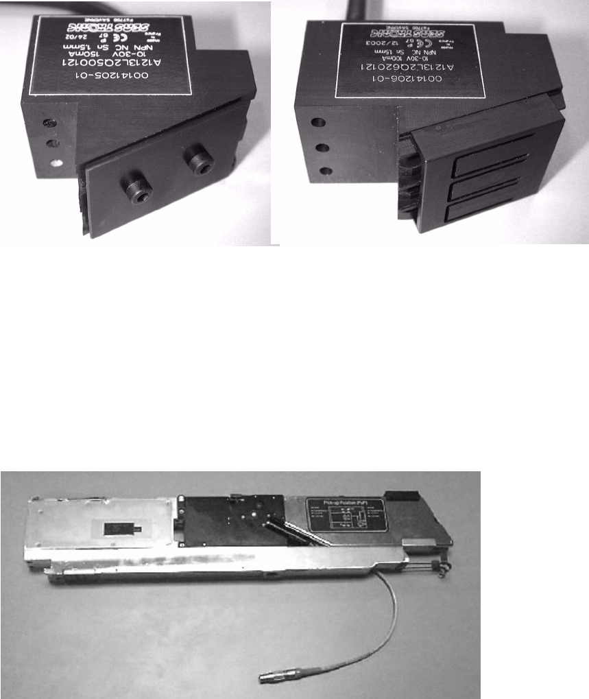
: Read the retrofit instructions and familiarize yourself with the splice sensor for 2x8 mm or 3x8
mm feeders.
3
Fig. 3 - 1 Splice sensors for 8 mm feeders
3.6 Installation
: Open the protective cover.
: Remove the 2x8 mm or 3x8 mm feeder from the machine.
3
Fig. 3 - 2 2x8 mm feeder
3
Splice sensor 2x8 mm
Splice sensor 3x8 mm
Retrofit instructions Splice sensors 8 - 72 mm
07/2003 Edition
20
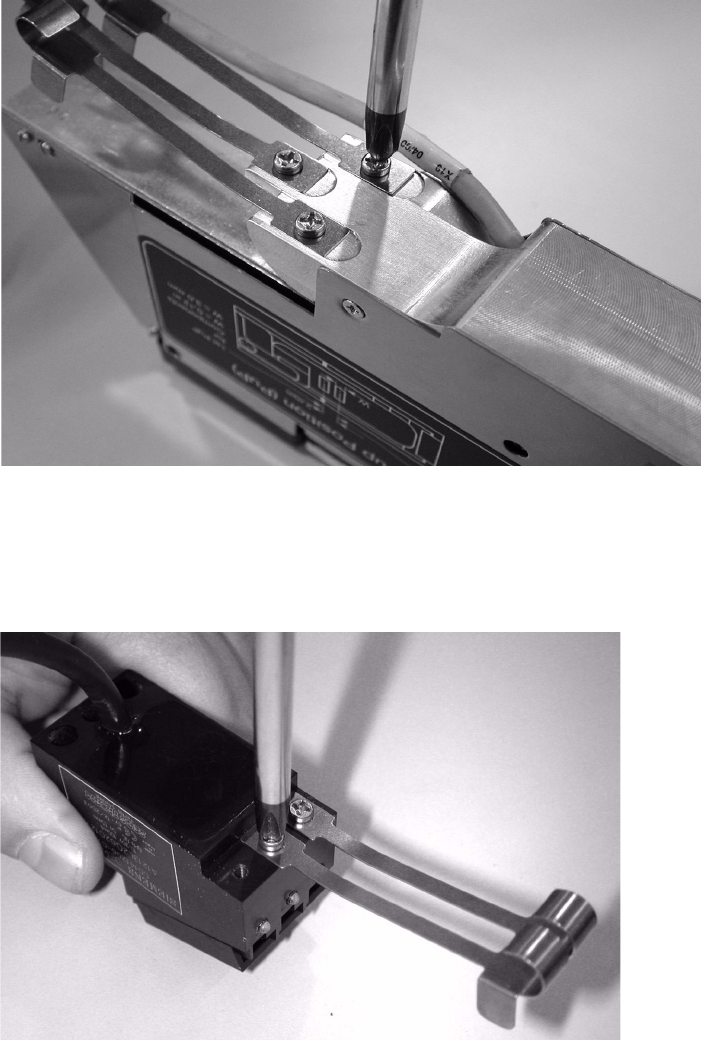
: Remove the tape guide plate from the feeder.
3
Fig. 3 - 3 Unscrewing the tape guide plate
3
: Fix the tape guide plate to the sensor block using the same screw.
3
Fig. 3 - 4 Fixing the tape guide plate
3
3
3
Retrofit instructions Splice sensors 8 - 72 mm
07/2003 Edition
21
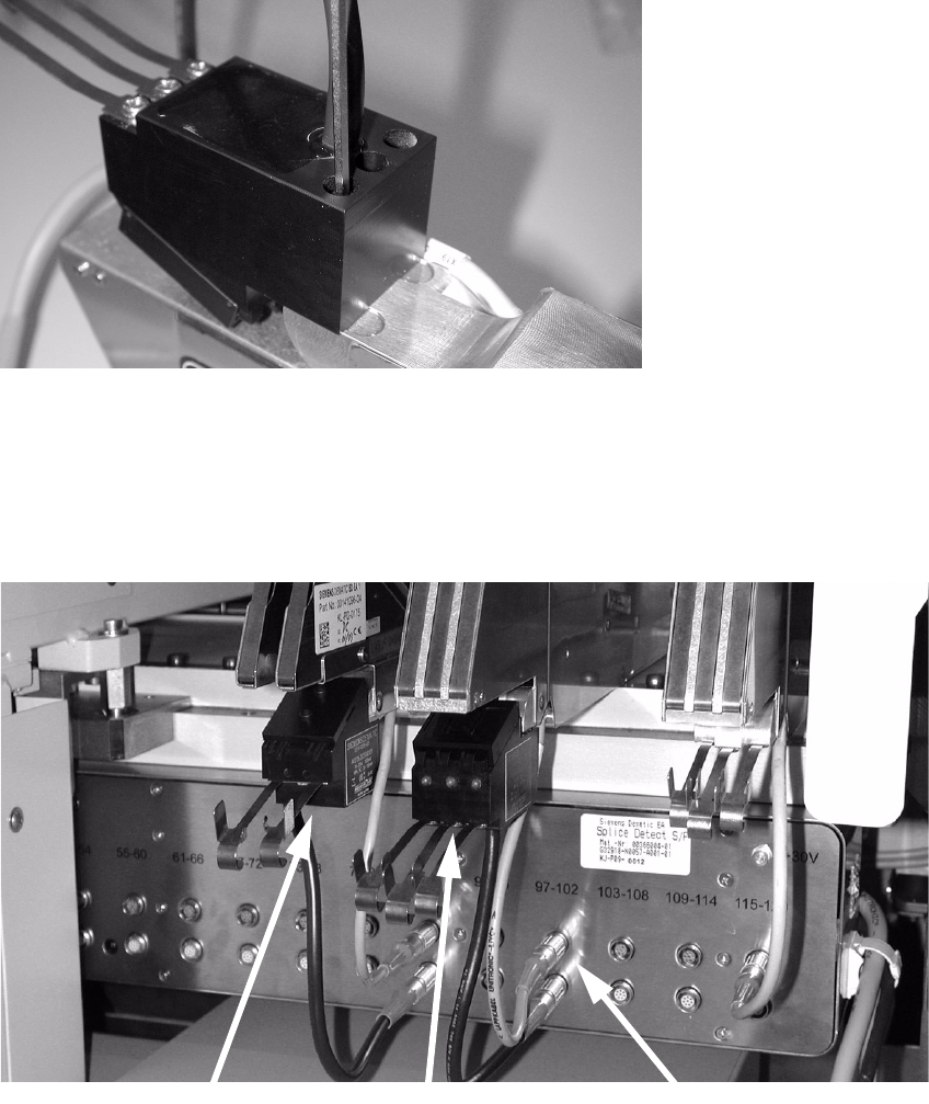
: Use the M3x25 mm screws to fix the sensor to the feeder at the point previously used to fix the
tape guide plate. You will need one or both screws, depending on the feeder.
3
Fig. 3 - 5 Fixing the sensor to the feeder
: Place the feeder back on the component feeder table and connect it up. Then place the splice
sensor in the appropriate socket on the lower socket block.
: Guide the tape over the tape guide plate into the sensor, and then through the feeder as usual.
3
Fig. 3 - 6 Feeder with splice sensors, connected
3
3
3x8 mm feeder
2x8 mm feeder
Terminals