00193365-0202.pdf - 第22页
Retrofit instructions Splice s ensors 8 - 72 m m 07/2003 Edition 22 The LEDs on the spli ce sensor s have the fo llowing mean ing: 3 – LED on: Ready – LED off: S plice d etected 3 Fig. 3 - 7 LEDs o n the splice sensor 3 …
Retrofit instructions Splice sensors 8 - 72 mm
07/2003 Edition
21
: Use the M3x25 mm screws to fix the sensor to the feeder at the point previously used to fix the
tape guide plate. You will need one or both screws, depending on the feeder.
3
Fig. 3 - 5 Fixing the sensor to the feeder
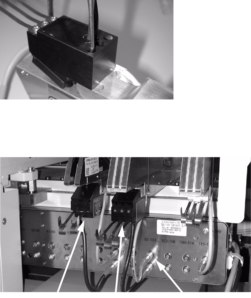
: Place the feeder back on the component feeder table and connect it up. Then place the splice
sensor in the appropriate socket on the lower socket block.
: Guide the tape over the tape guide plate into the sensor, and then through the feeder as usual.
3
Fig. 3 - 6 Feeder with splice sensors, connected
3
3
3x8 mm feeder
2x8 mm feeder
Terminals
Retrofit instructions Splice sensors 8 - 72 mm
07/2003 Edition
22
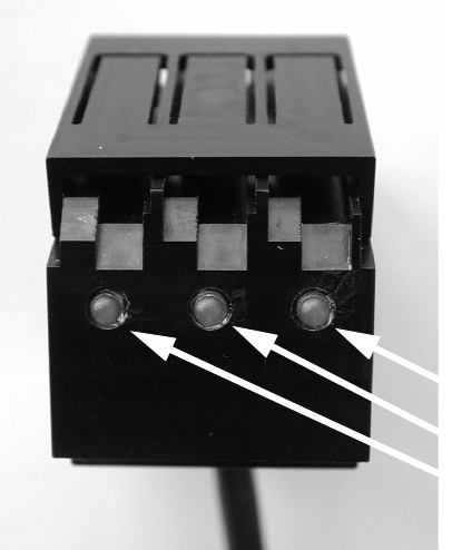
The LEDs on the splice sensors have the following meaning: 3
– LED on: Ready
– LED off: Splice detected
3
Fig. 3 - 7 LEDs on the splice sensor
3
3
LEDs
Retrofit instructions Splice sensors 8 - 72 mm
07/2003 Edition
23
4 Splice sensors for 12/16, 24/32, 44, 56 and 72 mm
feeders
4.1 Restrictions
– The "pocket in pocket"-splice method is not released for splice detection, because it can cause
defects and tailbacks.
– From 32 mm tape upwards a spring has to be inserted to keep the tape over the sensor (see
Fig. 4 - 5).
– Please note that the Splice Detect Sensor cannot handle tapes that contain metal material.
– If you return a defective feeder, please remove the Splice Detect Sensor. If you return a feeder
with the Splice Detect Sensor still attached, there is no guarantee that you will get Splice Detect
Sensor returned to you.
– Please note that splices must have their string of brass on the bottom of the tape.
4.2 Preparations
: Check that all of the parts are present and that you have the proper tools for installation.
: Become familiar with the Splice Detect Sensor and it’s construction as shown in Fig. 4 - 1.
: Remove the feeder from the changeover table before starting procedure. Remove the feeder
cable from the table connection.