00193365-0202.pdf - 第23页
Retrofit instructions Splice sensors 8 - 72 mm 07/2003 Edition 23 4 S plice sensors for 12/16, 2 4/32, 44, 56 and 72 mm feeders 4.1 Restrict ions – The " pocke t i n pocket"-splice meth od i s n ot r e leased f…
Retrofit instructions Splice sensors 8 - 72 mm
07/2003 Edition
22
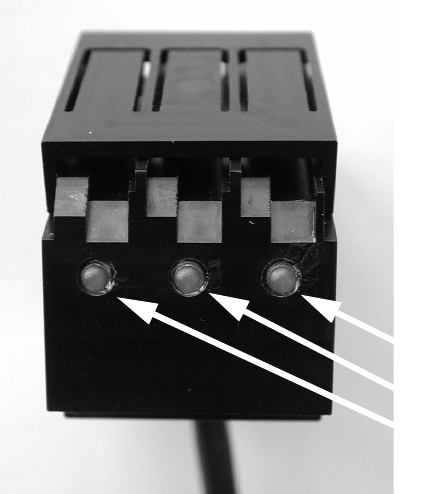
The LEDs on the splice sensors have the following meaning: 3
– LED on: Ready
– LED off: Splice detected
3
Fig. 3 - 7 LEDs on the splice sensor
3
3
LEDs
Retrofit instructions Splice sensors 8 - 72 mm
07/2003 Edition
23
4 Splice sensors for 12/16, 24/32, 44, 56 and 72 mm
feeders
4.1 Restrictions
– The "pocket in pocket"-splice method is not released for splice detection, because it can cause
defects and tailbacks.
– From 32 mm tape upwards a spring has to be inserted to keep the tape over the sensor (see
Fig. 4 - 5).
– Please note that the Splice Detect Sensor cannot handle tapes that contain metal material.
– If you return a defective feeder, please remove the Splice Detect Sensor. If you return a feeder
with the Splice Detect Sensor still attached, there is no guarantee that you will get Splice Detect
Sensor returned to you.
– Please note that splices must have their string of brass on the bottom of the tape.
4.2 Preparations
: Check that all of the parts are present and that you have the proper tools for installation.
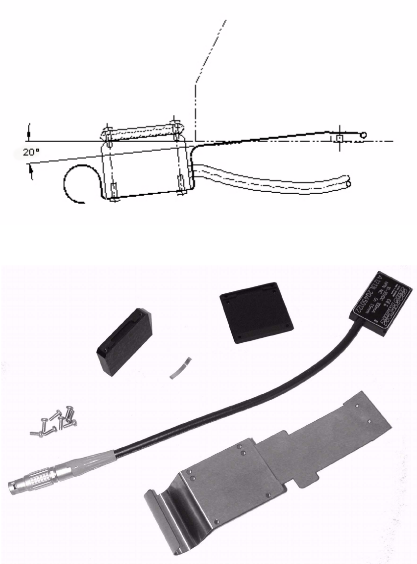
: Become familiar with the Splice Detect Sensor and it’s construction as shown in Fig. 4 - 1.
: Remove the feeder from the changeover table before starting procedure. Remove the feeder
cable from the table connection.
Retrofit instructions Splice sensors 8 - 72 mm
07/2003 Edition
24
4
Fig. 4 - 1 Splice Detect Sensor (similar for all sizes)
4
Fig. 4 - 2 Parts