00193365-0202.pdf - 第24页
Retrofit instructions Splice s ensors 8 - 72 m m 07/2003 Edition 24 4 Fig. 4 - 1 Splice Detect Sensor (similar for all s izes) 4 Fig. 4 - 2 Parts
Retrofit instructions Splice sensors 8 - 72 mm
07/2003 Edition
23
4 Splice sensors for 12/16, 24/32, 44, 56 and 72 mm
feeders
4.1 Restrictions
– The "pocket in pocket"-splice method is not released for splice detection, because it can cause
defects and tailbacks.
– From 32 mm tape upwards a spring has to be inserted to keep the tape over the sensor (see
Fig. 4 - 5).
– Please note that the Splice Detect Sensor cannot handle tapes that contain metal material.
– If you return a defective feeder, please remove the Splice Detect Sensor. If you return a feeder
with the Splice Detect Sensor still attached, there is no guarantee that you will get Splice Detect
Sensor returned to you.
– Please note that splices must have their string of brass on the bottom of the tape.
4.2 Preparations
: Check that all of the parts are present and that you have the proper tools for installation.
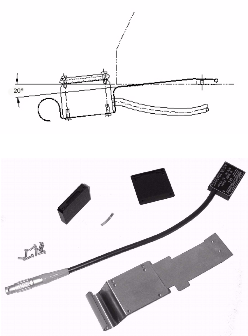
: Become familiar with the Splice Detect Sensor and it’s construction as shown in Fig. 4 - 1.
: Remove the feeder from the changeover table before starting procedure. Remove the feeder
cable from the table connection.
Retrofit instructions Splice sensors 8 - 72 mm
07/2003 Edition
24
4
Fig. 4 - 1 Splice Detect Sensor (similar for all sizes)
4
Fig. 4 - 2 Parts
Retrofit instructions Splice sensors 8 - 72 mm
07/2003 Edition
25
4.3 Installation Instructions
Prepare feeder 4
: After removal of feeder, remove (2) phillips head screws holding the communications cable
bracket, and save bracket with screws.
4
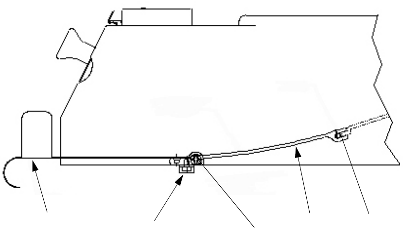
Fig. 4 - 3 Removal of existing spring guide and holding bracket
4
: Remove (2) side phillips head screws, one each side of Feeder, holding the tape guide spring
holding bracket inside of the feeder.
Save these screws.
: Pull the bracket straight out towards the rear of the feeder. Pivot up and down slightly to loosen
bracket as you pull.
The bracket may be tight and difficult to remove, but it does come out.
: Pull bracket and spring completely out of feeder.
4
: Remove the (2) M3 x 4 flat head screws holding the tape guide spring and discard the spring,
but save these (2) screws. See Fig. 4 - 1.
4
4
Pins
Holding
bracket
Phillips head
screws
Tape guide
spring
Comm.cable holding
bracket w/screws