00194932-20 User Manual CAN Test Box-Error Frame Diagnostic unit_en.pdf - 第125页
1 - 125 Edition 10/2 018 SIPLACE CAN Bus 125 4.15.1 Machine CAN Bu s structure X4 S and X4i S (V ariant 1 until Sept. 2013) With the new closed loop concept GCU (Gantry control un it) for the main axes and HCU/MHCU (Head…
1 - 124
SIPLACE CAN Bus Edition 10/2018
124
4.15 CAN Bus structure SIPLACE X-Serie S
X-Serie S machine operate with two separate CAN Bus networks (CAN1 / CAN2).
Both networks have a speed of 1MBit/s.
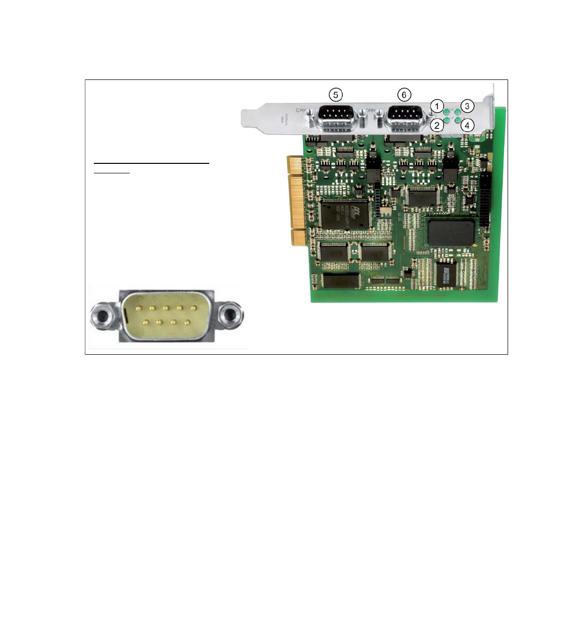
CAN Bus card in the Box PC 827C 4
The CAN Bus card COM168V2-PCI (03079973) is a PCI plug-in card and is located in the BoxPC.
For easy accessible service on both connected machine CAN cables (CAN 1 / CAN 2) there is an
SUB-D9 connector attached.
Fig. 4.15 - 1 CAN Bus card COM168V2-PCI (03079973-0x)
(1) L1- flash, during the canals will be initiali-
zed, after that the LED is ON (RUN Status)
(2) L2 - flash
(3) L3 - shows communication on CAN Bus 1 (4) L4 - shows communication on CAN Bus 2
(5) CAN 1 - connector CAN Bus 1 for PA1 (6) CAN 2 - connector CAN Bus 2 for PA2
Pin assignment of the SUB-D9
interface:
PIN 1 – not used
PIN 2 – CAN Low
PIN 3 – CAN Ground
PIN 4 – not used
PIN 5 – not used
PIN 6 – CAN Ground
PIN 7 – CAN High
PIN 8 – not used
PIN 9 – not used
1 - 125
Edition 10/2018 SIPLACE CAN Bus
125
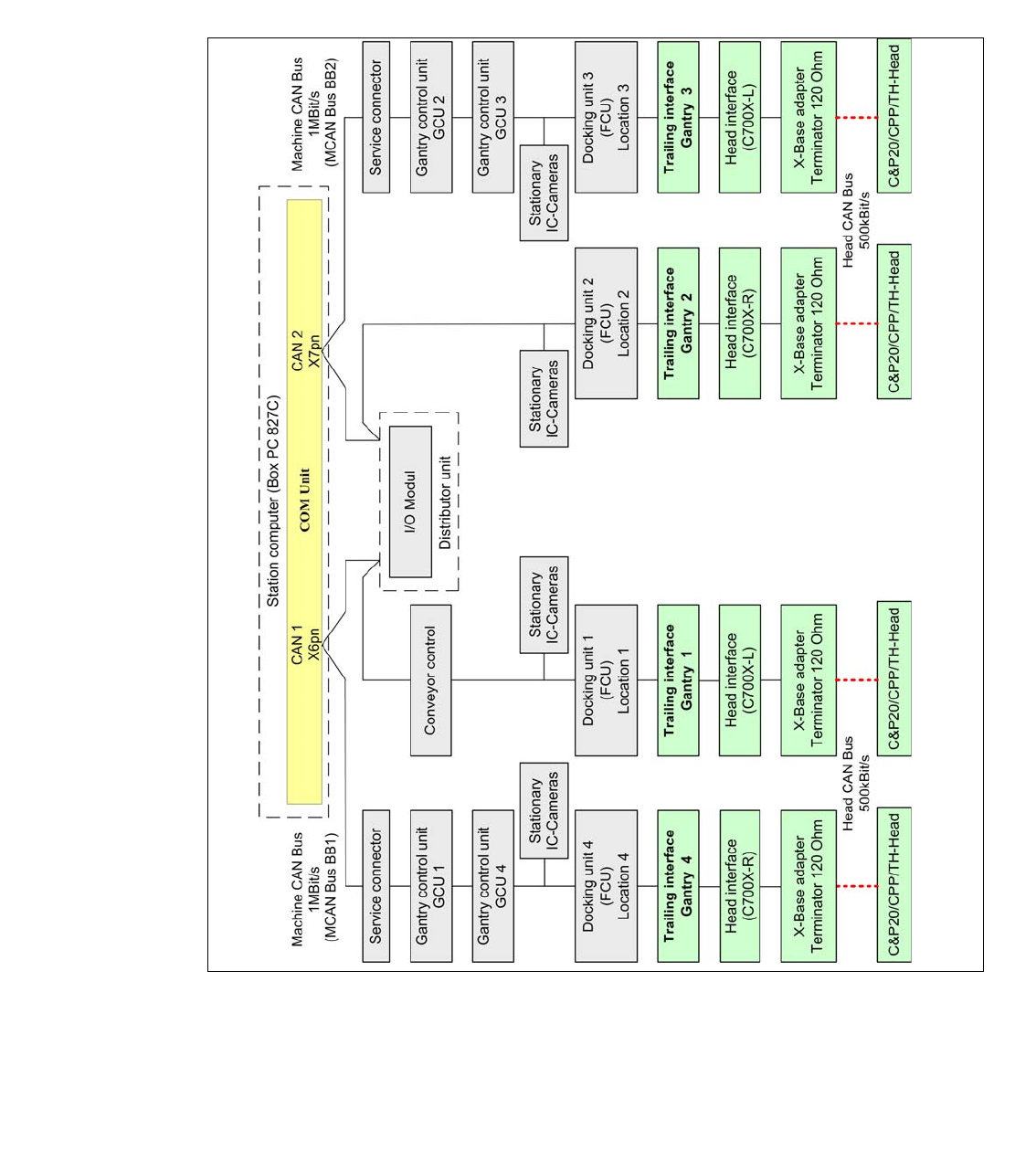
4.15.1 Machine CAN Bus structure X4 S and X4i S (Variant 1 until Sept. 2013)
With the new closed loop concept GCU (Gantry control unit) for the main axes and HCU/MHCU
(Head control unit/Modular Head Control Unit) for the head axes, follow a new Can Bus structure,
which include these subsystems. In the circuit digram called MCAN Bus (Machine CAN Bus). To
synchronize the HCU‘s and GCU‘s an additional CAN Bus, called GCAN Bus (Gantry CAN Bus)
was introduced.
Fig. 4.15 - 2 CAN Bus SIPLACE X4 S and X4i S (Variant 1)
1 - 126
SIPLACE CAN Bus Edition 10/2018
126
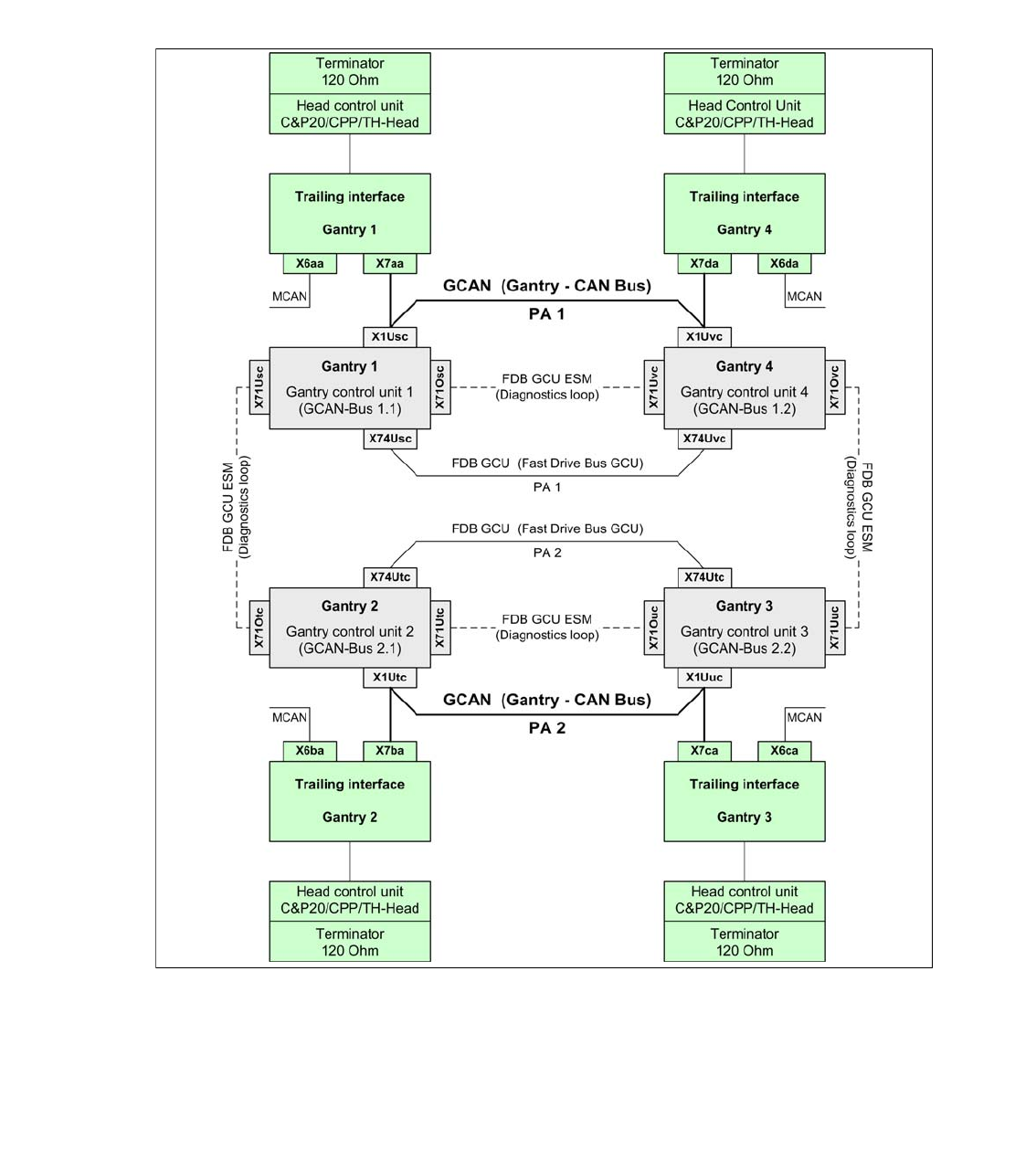
4.15.2 Gantry CAN Bus SIPLACE X4 S and X4i S
The GCAN-Bus is responsible for the communication between the gantry control unit‘s (GCU´s)
and the Head Control Units (HCU´s/MHCU‘s) for gantries in one placement area (e.g. Head-CAN-
Diagnose or SIRIO-communication).
In case of troubleshooting, machine problems or swap connectors you have to know and check
the Gantry CAN Bus, too. (see circuit diagram, too)
Fig. 4.15 - 3 Gantry CAN Bus SIPLACE X4 S and X4i S