00194932-20 User Manual CAN Test Box-Error Frame Diagnostic unit_en.pdf - 第140页
1 - 140 SIPLACE CAN Bus Edition 10/2018 140 4.16.1 Machine CAN Bus structure X4i S and X4 S (from MA No.H001/May 2015) The CIN Bo x with 4 CAN Bu s connector s are able to support ea ch location v ia one CAN Bus con- net…
1 - 139
Edition 10/2018 SIPLACE CAN Bus
139
4.16 CAN Bus structure SIPLACE X-Serie S (from MA
No.H001/May 2015)
All X-Series S machine with serial number H001, delivered since may 2015 are provided with new
hardware:
- Box PC 427d with Core 3i-Processor
- CIN Box 4 fold CAN Bus card
- MGCU2/MGCU3 - Modulare Gantry Control Unit
- Power supply unit - Switched Module Power Supply (SMPS)
- I/O Module 2
- Vision Gig E - Cameras (PCB-Camera, Component-Camera and stationary Cameras)
- changed trailling harness
With the introduction of the CAN Interface (03108598-xx CAN Interface CINX) the CAN structure
of the X-Series S machine have changed. This changes are described of the following pages.
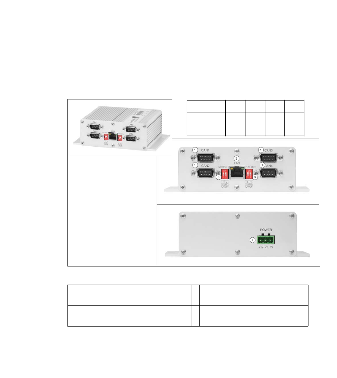
Fig. 4.16 - 1 03108598-xx CAN Interface CINX
1 CAN Bus Connector CAN1-4 2 LAN Connector CAT 5 cable to PC
LAN1
3 DIP Switch - setting the terminator of 120
Ohm for CAN1-4
4 Power connector 24V
1234
X-Series SONONONON
SX-Series OFF OFF OFF OFF
1 - 140
SIPLACE CAN Bus Edition 10/2018
140
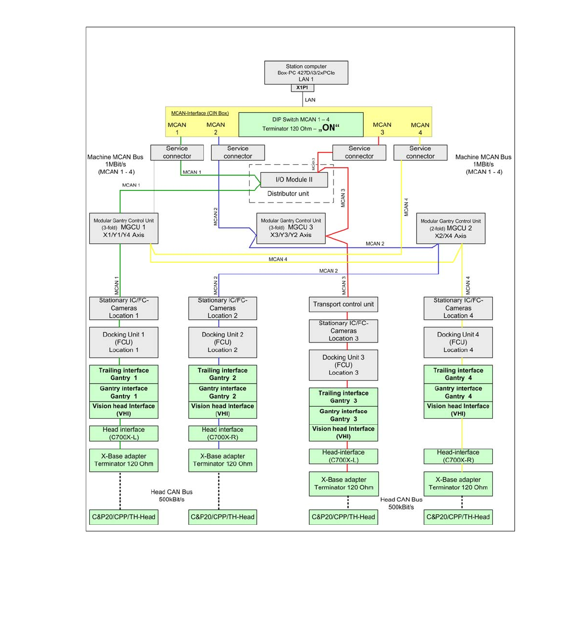
4.16.1 Machine CAN Bus structure X4i S and X4 S (from MA No.H001/May 2015)
The CIN Box with 4 CAN Bus connectors are able to support each location via one CAN Bus con-
netor. Therefore the physical lenght of the CAN Bus cable could reduce, so this improved the qua-
lity of the CAN Bus communication between the CIN Box and the other subsystems.
In case of troubleshooting of the CAN Bus, it is important to know the wiring between the MGCU‘s.
This is the result from the differnt number of gantries and the 2-fold and 3-fold MGCU.
Fig. 4.16 - 2 Machine CAN Bus X4i S and X4 S
1 - 141
Edition 10/2018 SIPLACE CAN Bus
141
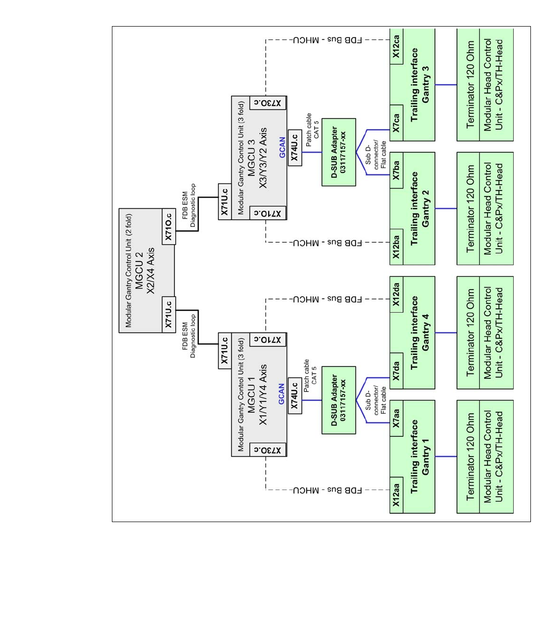
4.16.2 Gantry CAN Bus SIPLACE X4i S and X4 S (from MA No.H001/May 2015)
The GCAN-Bus is responsible for the communication between the Modular Gantry Control Unit‘s
(MGCU´s/) and the Modular Head Control Units (MHCU‘s) for gantries in one placement area (e.g.
Head-CAN-Diagnose or SIRIO-communication).
In case of troubleshooting, machine problems or swap connectors you have to know and check
the Gantry CAN Bus, too. (see circuit diagram)
Fig. 4.16 - 3 Gantry CAN Bus SIPLACE X4i S and X4 S