00194932-20 User Manual CAN Test Box-Error Frame Diagnostic unit_en.pdf - 第15页
1 - 15 Edition 10/2 018 SIPLACE CAN Bus 15 – BNC socket for power fail to check of the level in the line (4,0 - 5,0 V). – BNC socket for CAN reset to check of the level in the line (4,0 - 5,0 V). 2.4 Checking the T ermin…
1 - 14
SIPLACE CAN Bus Edition 10/2018
14
2.3 CAN Test Box Connections
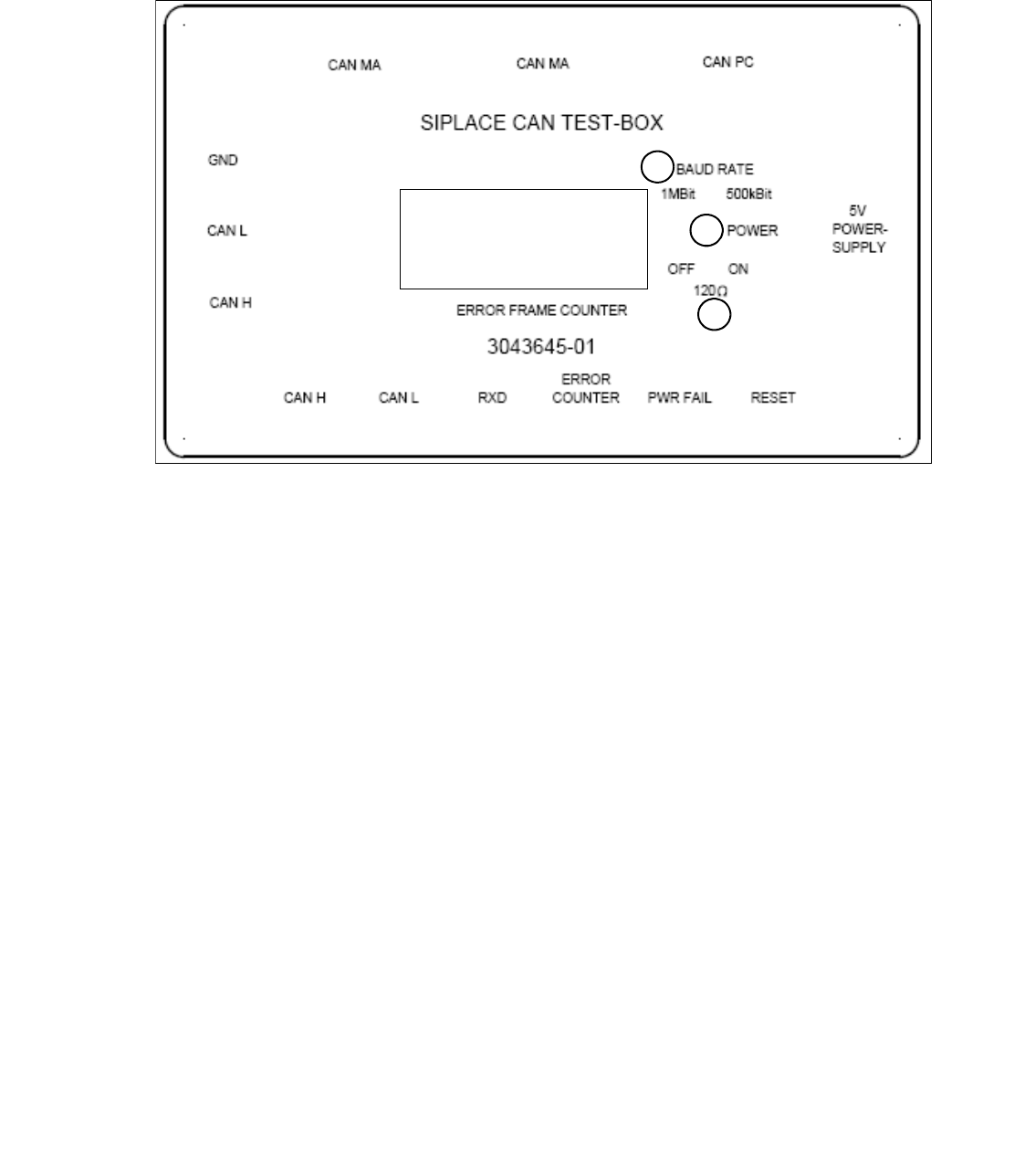
Fig. 2.3 - 1 CAN Test Box connections
(1) Switch for setting the baud rate to 1 MBit or 500 kBit
(2) Switch for enabling an additional 120 Ohm resistance.
(3) Power LED to show the power supply state (green = power on)
– 5V voltage supply from the axis card or external power pack
– CAN BUS PC connection PC (Sub D female connector). Only the CAN High, CAN Low and
GND signals are run to the PC (Kvaser card), preventing PC-card corruption.
– CAN BUS_MA connection to the machine, COM assembly (Sub D female connector)
– CAN BUS_MA connection to the machine, COM assembly (Sub D male connector)
– Banana jack for CAN High measurement of recessive CAN bus level against CAN GND
– Banana jack for CAN Low measurement of recessive CAN bus level against CAN GND
– Banana jack for CAN GND ground CAN bus
– BNC socket for CAN High
– BNC socket for CAN Low
– BNC socket RxD shows the combination of CAN High and CAN Low signals to a TTL level, as
read by the CAN telegram processor.
– BNC socket for Error Counter from display
Error Frame Counter
Display
1
3
2
1 - 15
Edition 10/2018 SIPLACE CAN Bus
15
– BNC socket for power fail to check of the level in the line (4,0 - 5,0 V).
– BNC socket for CAN reset to check of the level in the line (4,0 - 5,0 V).
2.4 Checking the Terminating Resistors
To avoid reflection in the CAN lines, a 120 Ohm terminating resistor must be placed at each end
of the CAN bus wire, between CAN_H and CAN_L. A correctly closed CAN bus will have a resis-
tance value of 60 Ohm. An additional terminating resistor reduces the overall resistance to 40
Ohm.
If the resistors are not placed at the end points, the CAN lines will experience reflections. The ef-
fect of incorrect terminating resistors can be seen in the appropriate diagram in this chapter.
Step by step: 2
Attention: 2
When connecting the CAN Test Box, make sure the switches for the baud rate and terminating
resistors are set to the correct values (default setting for the terminating resistor is OFF)
(see Fig. 2.3 - 1 number 2).
Note:
Make sure that the machine is switched off before measurement is performed!
Attention: 2
Connection the CAN Test Box: To measure all signals on the CAN Test Box you have to use a
CAN Test cable connect directly on the COM board, connect the machine CAN cable on the
testing cable and then the CAN Test box.
On the Service connector are not all signals!
– Connect the CAN Test Box to the service plug (Note: Not all signals on the Service plug) of the
COM assembly.
– Measure the CAN bus resistance at the banana sockets between CAN H and CAN L, with the
help of a measuring device.
A correct CAN bus resistance will have a value of 60 Ohm.
If errors occur, check the resistors.
Note:

1 - 16
SIPLACE CAN Bus Edition 10/2018
16
For the positions of the terminating resistors, refer to Chapter 1.9 CAN Bus Operation Diagrams.