00194932-20 User Manual CAN Test Box-Error Frame Diagnostic unit_en.pdf - 第155页
1 - 155 Edition 10/2 018 SIPLACE CAN Bus 155 4.18.2 Gantry CAN Bus TX2i and TX2 The GCAN-Bus is responsible for the communica t ion between the Mo dular Gantry Control Unit‘s (MGCU´s) and the Mo dular Head Control Units …
1 - 154
SIPLACE CAN Bus Edition 10/2018
154
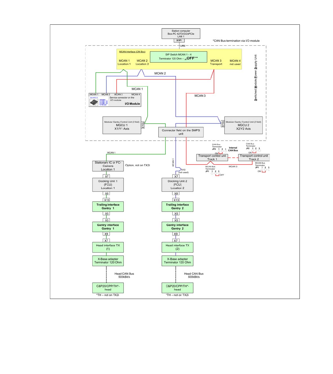
4.18.1 Machine CAN Bus Structure TX2i and TX2
On the SIPLACE TX Machine there are three CAN Bus networks which communicate to the sub-
systems.The service connector for each CAN Bus network are placed directly on the I/O module.
The following overview shows the structure of the CAN Bus. The MCAN 1 communicate with all
subsystems in location 1 (MGCU, FCU, stationary camera, gantry 1). The MCAN 2 communicate
with all subsystems in location 2 (MGCU, FCU, gantry 2) and the MCAN 3 is responsible for the
Transport control unit.
Fig. 4.18 - 2 Machine CAN Bus SIPLACE TX2i and TX2
1 - 155
Edition 10/2018 SIPLACE CAN Bus
155
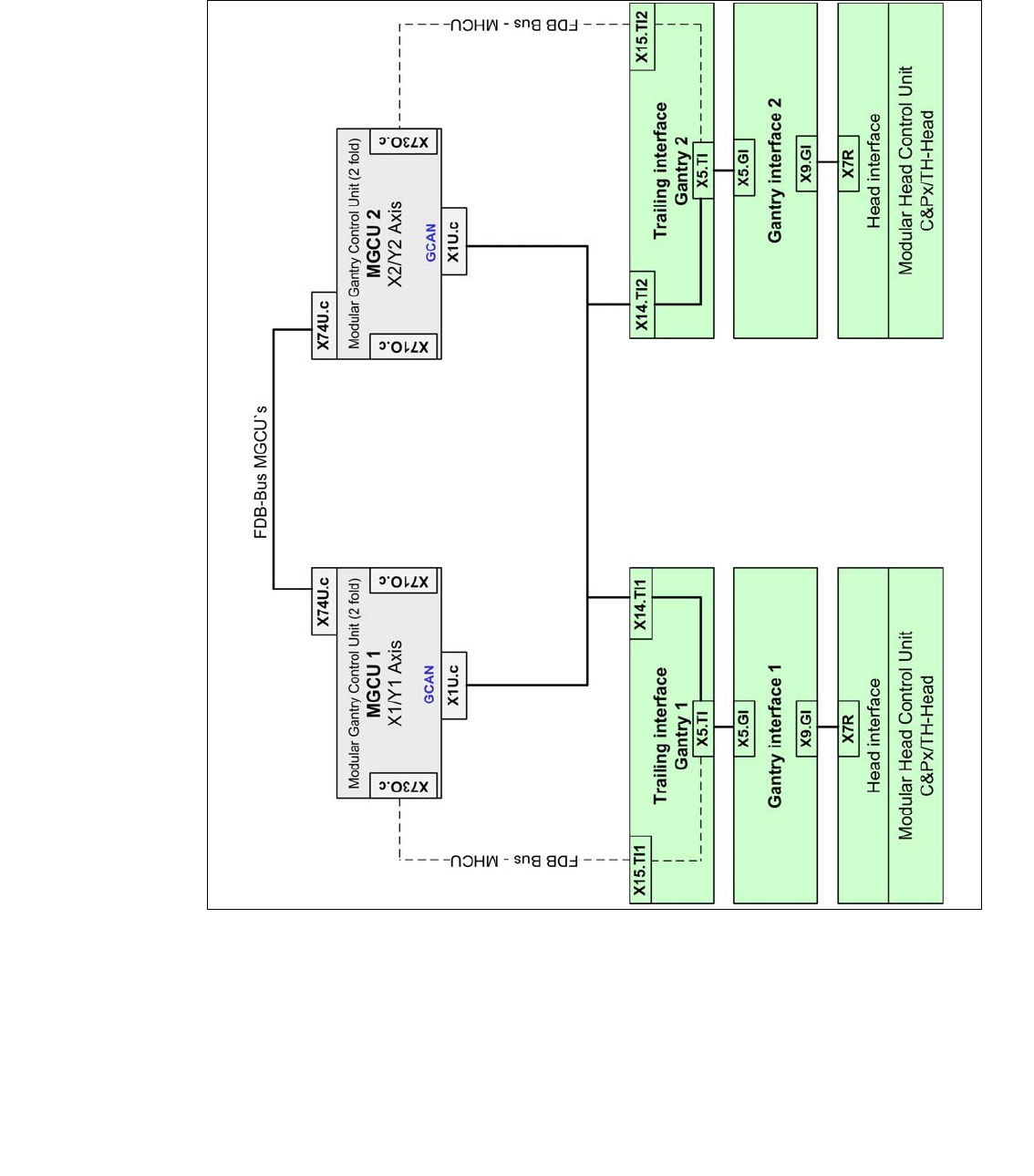
4.18.2 Gantry CAN Bus TX2i and TX2
The GCAN-Bus is responsible for the communication between the Modular Gantry Control Unit‘s
(MGCU´s) and the Modular Head Control Units (MHCU‘s) for gantries in one placement area (e.g.
Head-CAN-Diagnose or SIRIO-communication).
Fig. 4.18 - 3 Gantry CAN Bus SIPLACE TX2i and TX2
1 - 156
SIPLACE CAN Bus Edition 10/2018
156
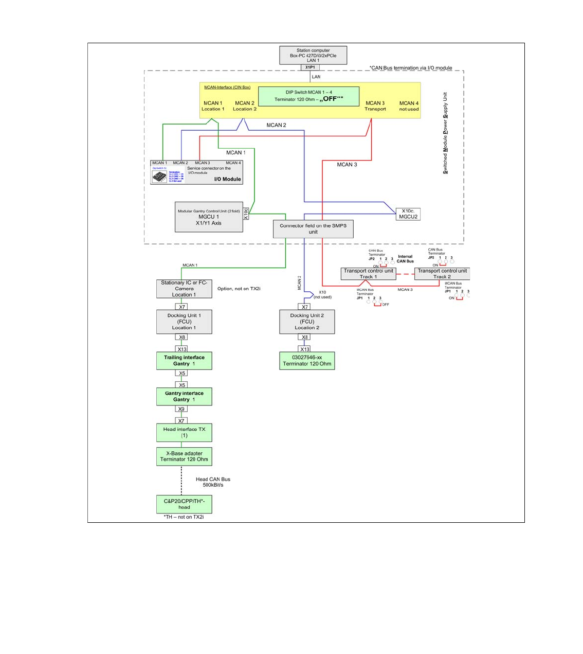
4.18.3 Machine CAN Bus Structure TX1
On the SIPLACE TX Machine there are three CAN Bus networks which communicate to the sub-
systems.The service connector for each CAN Bus network are placed directly on the I/O module.
The following overview shows the structure of the CAN Bus. The MCAN 1 communicate with all
subsystems in location 1 (MGCU, FCU, stationary camera, gantry 1). The MCAN 2 communicate
with all subsystems in location 2 (MGCU, FCU, gantry 2) and the MCAN 3 is responsible for the
Transport control unit.
Fig. 4.18 - 4 Machine CAN Bus SIPLACE TX1