00194932-20 User Manual CAN Test Box-Error Frame Diagnostic unit_en.pdf - 第163页
1 - 163 Edition 10/2 018 SIPLACE CAN Bus 163 Fig. 4.19 - 5 Machine CAN Bus SIPLACE TX1 circuit diagram9001 2154-01 *&$1 *&$1 *&$1 *&$1 &$1EXVZLULQJ &$1EXVZLULQJ &$1EXVZLULQJ &$1EXV…
1 - 162
SIPLACE CAN Bus Edition 10/2018
162
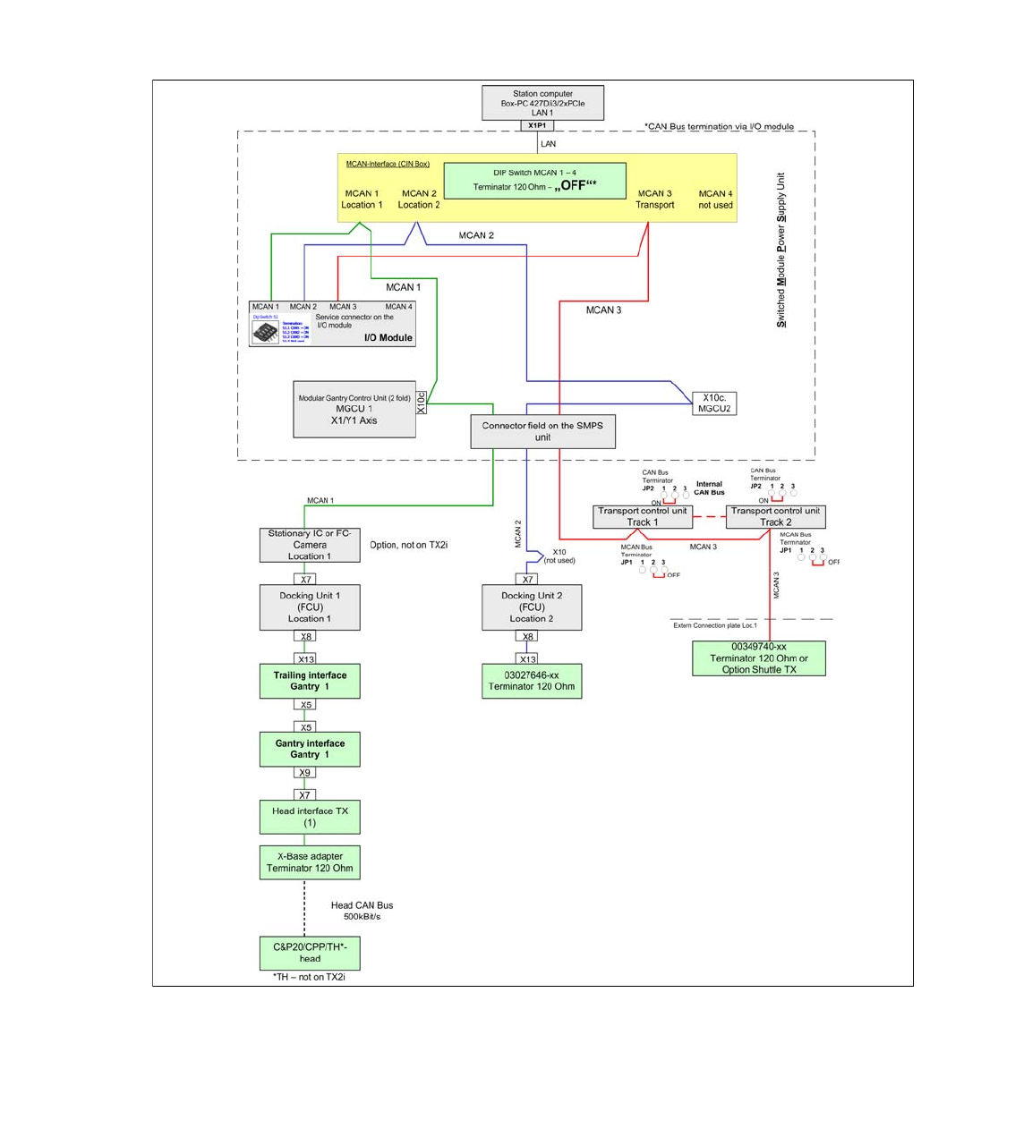
4.19.2 Machine CAN Bus Structure TX1 (from MA No. TA 500 January 2015)
On the SIPLACE TX Machine there are three CAN Bus networks which communicate to the sub-
systems.The service connector for each CAN Bus network are placed directly on the I/O module.
The following overview shows the structure of the CAN Bus. The MCAN 1 communicate with all
subsystems in location 1 (MGCU, FCU, stationary camera, gantry 1). The MCAN 2 communicate
with all subsystems in location 2 (MGCU, FCU, gantry 2) and the MCAN 3 is responsible for the
Transport control unit and the option shuttle extension TX.
Changes to the previous version of TX, is the Jumper setting on the TSP track 2 and an additional
Terminator.
Fig. 4.19 - 4 Machine CAN Bus SIPLACE TX1
1 - 163
Edition 10/2018 SIPLACE CAN Bus
163
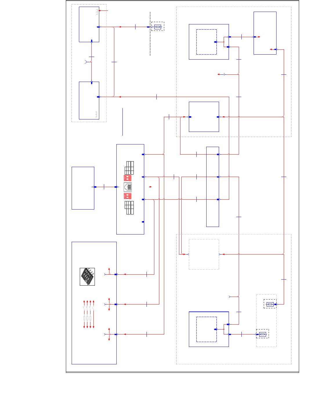
Fig. 4.19 - 5 Machine CAN Bus SIPLACE TX1 circuit diagram90012154-01
*&$1
*&$1
*&$1
*&$1
&$1EXVZLULQJ
&$1EXVZLULQJ
&$1EXVZLULQJ
&$1EXVZLULQJ
:LUHQRZLULQJ'6XESLQ
1&
*1'
&$1B/
&$1B+
*1'
1&
1&
1&
1&
0&$1/RFDWLRQ
0&$1/RFDWLRQ
0&$1/RFDWLRQ
0&$1/RFDWLRQ0&$1/RFDWLRQ
0&$1/RFDWLRQ
0&$1/RFDWLRQ
0&$1/RFDWLRQ
QRWXVHG
7HUPLQDWLRQ
7HUPLQDWLRQ
7HUPLQDWLRQ
7HUPLQDWLRQ
6&$1 21
6&$1 21
6&$1 21
6&$1 21
6&$1 21
6&$1 21
6&$1 21
6&$1 21
6&$1 21
6&$1 21
6&$1 21
6&$1 21
61RWXVHG
61RWXVHG
61RWXVHG
61RWXVHG
&$1%XVWHUPLQDWLRQ
&$1%XVWHUPLQDWLRQ
&$1%XVWHUPLQDWLRQ
&$1%XVWHUPLQDWLRQ
'LS6ZLWFK6
'XDO&RQYH\RU
'XDO&RQYH\RU
'XDO&RQYH\RU
'XDO&RQYH\RU
21 21
2)) 2))
;6HU6
6;
21 21
2)) 2))
;6HU6
6;
/$12KP 2KP
2))
2))
2))
2)) 2))
2))
2))
2))7;
7;
7;
7; 2))
2))
2))
2)) 2))
2))
2))
2)) 7;
7;
7;
7;
1RWH
1RWH
1RWH
1RWH
7HUPLQDWLRQYLD,2B'LVWULEXWRUBERDUG
7HUPLQDWLRQYLD,2B'LVWULEXWRUBERDUG
7HUPLQDWLRQYLD,2B'LVWULEXWRUBERDUG
7HUPLQDWLRQYLD,2B'LVWULEXWRUBERDUG
([WHUQ&RQQHFWRUSODWH
0*&8
QRWXVHG
*DQWU\
QRWPRXQWHG
3&
3&
3&
3&
&RQWURO&RPSXWRU
&RQWUROFRPSXWHU%R[3&'L[3&,H
&RQWUROFRPSXWHU%R[3&'L[3&,H
&RQWUROFRPSXWHU%R[3&'L[3&,H
&RQWUROFRPSXWHU%R[3&'L[3&,H
&+&75/
',
',
',
',
,2FRQWUROXQLW
,2FRQWUROXQLW
,2FRQWUROXQLW
,2FRQWUROXQLW
'LVWULEXWRUDVVHPEO\7;
'LVWULEXWRUDVVHPEO\7;
'LVWULEXWRUDVVHPEO\7;
'LVWULEXWRUDVVHPEO\7;
'LVWULEXWRU
',
;3
;3
;3
;3
/$1
;
;
;
;
&$1
&$1&,1
&$1&,1
&$1&,1
&$1&,1
;B&$1',
;B&$1',
;B&$1',
;B&$1',
:
:
:
:
)ODWURXQGFDEOH
[
PP
0*&8
0*&8
0*&8
0*&8
*DQWU\
3RVLWLRQFRQWUROOHU
3RVLWLRQFRQWUROOHU
3RVLWLRQFRQWUROOHU
3RVLWLRQFRQWUROOHU
JDQWU\D[LV0*&8
JDQWU\D[LV0*&8
JDQWU\D[LV0*&8
JDQWU\D[LV0*&8
&+*$
;2F
;2F
;2F
;2F
0&$1&$1
;2F0*&8
;2F0*&8
;2F0*&8
;2F0*&8
;&27L
;&27L
;&27L
;&27L
:
:
:
:
)ODWURXQGFDEOH
[
PP
;B&$1',
;B&$1',
;B&$1',
;B&$1',
&$1&,1
&$1&,1
&$1&,1
&$1&,1
;2F0*&8
;2F0*&8
;2F0*&8
;2F0*&8
;8F
;8F
;8F
;8F
*&$1
;7,
;7,
;7,
;7,
:
:
:
:
)ODWURXQGFDEOH
[
PP
;&27L
;&27L
;&27L
;&27L ;&27L
;&27L
;&27L
;&27L
PP
[
)ODWURXQGFDEOH
:
:
:
:
;
;
;
;
*&$1
;7,
;7,
;7,
;7,
;,&
;,&
;,&
;,&
;,&
;,&
;,&
;,&
:
:
:
:
)ODWURXQGFDEOH
[
PP
7,
7,
7,
7,
*DQWU\
7UDLOLQJLQWHUIDFH
7UDLOLQJLQWHUIDFH
7UDLOLQJLQWHUIDFH
7UDLOLQJLQWHUIDFH
&+*$
;8F0*&8
;8F0*&8
;8F0*&8
;8F0*&8
;7,
;7,
;7,
;7,
;8F0*&8
;8F0*&8
;8F0*&8
;8F0*&8
PP
[
)ODWURXQGFDEOH
:
:
:
:
PP
[
)ODWURXQGFDEOH
:
:
:
:
:
:
:
:
)ODWURXQGFDEOH
[
PP
:
:
:
:
)ODWURXQGFDEOH
[
PP
:
:
:
:
)ODWURXQGFDEOH
[
PP
:
:
:
:
)ODWURXQGFDEOH
[
PP
:
:
:
:
)ODWURXQGFDEOH
[
PP
;&27L
;&27L
;&27L
;&27L
;7,
;7,
;7,
;7,
;B&$1',
;B&$1',
;B&$1',
;B&$1',
:
:
:
:
)ODWURXQGFDEOH
[
PP
&$1&,1
&$1&,1
&$1&,1
&$1&,1
',&
',&
',&
',&
&RQQHFWRUILHOG
&+',
&$1',&
&$1',&
&$1',&
&$1',&&$1',&
&$1',&
&$1',&
&$1',&&$1',&
&$1',&
&$1',&
&$1',&
&$1',&
&$1',&
&$1',&
&$1',& &$1',&
&$1',&
&$1',&
&$1',&
:
:
:
:
)ODWURXQGFDEOH
[
PP
:
:
:
:
)ODWURXQGFDEOH
[
PP
:
:
:
:
)ODWURXQGFDEOH
[
PP
&$1',&
&$1',&
&$1',&
&$1',&
:
:
:
:
)ODWURXQGFDEOH
[
PP
:
:
:
:
)ODWURXQGFDEOH
[
PP
:
:
:
:
)ODWURXQGFDEOH
[
PP
&$7$6)735'
:
:
:
:
;33&
;33&
;33&
;33&
5-
/$1&,1
/$1&,1
/$1&,1
/$1&,1
5-
;B
;B
;B
;B
&$16HUYLFH
;
;
;
;
&$1
;
;
;
;
&$1
;B
;B
;B
;B
&$16HUYLFH
;B
;B
;B
;B
&$16HUYLFH
5
6
;)&8
;)&8
;)&8
;)&8
)&8
)&8
)&8
)&8
;)&89
/RFDWLRQ
&27L/RF
&27L
&27L
&27L
&27L
'RFNLQJXQLW
'RFNLQJXQLW
'RFNLQJXQLW
'RFNLQJXQLW
;
;
;
;
&$1B
>%DVHPDFKLQH@
;&27L
;&27L
;&27L
;&27L
&$1B,Q
;&27L
;&27L
;&27L
;&27L
&$1B2XW
;)&8
;)&8
;)&8
;)&8
)&8
)&8
)&8
)&8
;)&89
/RFDWLRQ
&27L/RF
&27L
&27L
&27L
&27L
'RFNLQJXQLW
'RFNLQJXQLW
'RFNLQJXQLW
'RFNLQJXQLW
;
;
;
;
&$1B
>%DVHPDFKLQH@
;&27L
;&27L
;&27L
;&27L
&$1B,Q
;&27L
;&27L
;&27L
;&27L
&$1B2XW
;
;
;
;
0&$1
&,1
&,1
&,1
&,1
&RQWURO&RPSXWRU
&$1,QWHUIDFH&,1
&$1,QWHUIDFH&,1
&$1,QWHUIDFH&,1
&$1,QWHUIDFH&,1
&+&75/
/$1
/$1
/$1
/$1
&$1
&$1
&$1
&$1
/RFDWLRQ
&$1
&$1
&$1
&$1
/RFDWLRQ
&$1
&$1
&$1
&$1
QRWXVHG
&$1
&$1
&$1
&$1
&RQYH\RU
:
:
:
:
)ODWURXQGFDEOH
[
PP
53LQ
;75
;75
;75
;75
7HUPLQDWLQJ
5HVLVWRU
53LQ
;75
;75
;75
;75
7HUPLQDWLQJ
5HVLVWRU
53LQ
;75
;75
;75
;75
7HUPLQDWRU2KP
'6XESLQIHPDOH
&$1(;7
&$1(;7
&$1(;7
&$1(;7
;&2$
;&2$
;&2$
;&2$
;&2$
;&2$
;&2$
;&2$
;
;
;
;
$
$
$
$
3&%/DQH
3&%/DQH
3&%/DQH
3&%/DQH
763[[
&2/
;
;
;
;
$
$
$
$
3&%/DQH
3&%/DQH
3&%/DQH
3&%/DQH
763[[
&2/
:
:
:
:
;6
;6
;6
;6
,QWHUQDO&$1%86
,QWHUQDO&$1%86
,QWHUQDO&$1%86
,QWHUQDO&$1%86
;
;
;
;
;$
;$
;$
;$
;$
;$
;$
;$
;
;
;
;
-3
-3
-3
-3
&$1EXVH[W
7HUPLQDWLRQ5
2))
7HUPLQDWLRQLVRQWKH
&RQQHFWRU&$1(;7
-3 2))
VWDUWLQJFDEOHH[WHQVLRQ:
-3
-3
-3
-3
&$1EXVH[W
7HUPLQDWLRQ5
2))
VW&$0/RF&$1
&$1B+
&$1B+
&$1B+
&$1B/
&$1B/
&$1B/
1& 1&
7HUPLQDWLRQ7HUPLQDWLRQ7HUPLQDWLRQ,2&2175 ,2&2175
*$0&$1
*$
(QG7HUPLQDWLRQ
*$*&$1
*$
(QG7HUPLQDWLRQ
&$1B%XVBZLULQJ
&$1B',
&$1B',
&$1B',
&$1/DQH
&2
*$0*&80&$1
&+*$
*$0*&8*&$1
&+*$
*$0*&80&$1
&+*$
*$0*&8*&$1
&+*$
&$1(;7
&2
1 - 164
SIPLACE CAN Bus Edition 10/2018
164
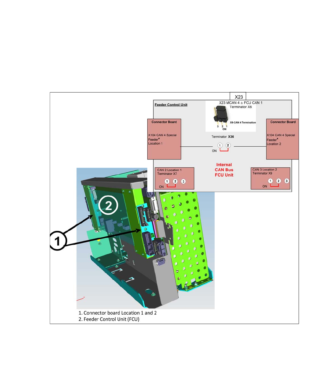
4.20 CAN Bus structure SIPLACE TX-Series Version 2
With the further development of the TX series (version 2) and the introduction of the SLIM FCU
on the COT insert, as well as the FCU (feeder control unit), a changed CAN bus structure results
between the subsystems.
The FCU is directly supplied with data via the CIN Box of the MCAN 4 as a subsystem. It consists
of one FCU board and one connection module each for the location 1 and 2
.
The FCU unit works with 4 independent CAN bus channels, which must be equipped with 120
Ohm terminating resistors, jumper setting on the FCU board..
FCU CAN Bus 1: MCAN 4 from the CIN Box - Terminator Jumper X6
FCU CAN Bus 2: Feeder CAN Bus location 1 with feeder, feeder unlock device, tape cutter, sen-
sor reject bin, nozzle changer, valve lock and unlock COT and nozzle station
FCU CAN Bus 3: Feeder CAN Bus Stellplatz 2 with feeder, feeder unlock device, tape cutter, sen-
sor reject bin, nozzle changer, valve lock and unlock COT and nozzle station
FCU CAN Bus 4: Special Feeder (JTF-ML2) - terminator Jumper X36
Fig. 4.20 - 1 CAN Bus connection FCU unit SIPLACE TX V2