00194932-20 User Manual CAN Test Box-Error Frame Diagnostic unit_en.pdf - 第21页
1 - 21 Edition 10/2 018 SIPLACE CAN Bus 21 Fig. 2.7 - 1 CAN telegram with error frame The Error Frame Coun ter switches, since one blo ck of the CAN telegr am (6 bi ts in this case) has maintained the same state fo r app…

1 - 20
SIPLACE CAN Bus Edition 10/2018
20
2.7 Checking the CAN Bus for Error Frames
What are error frames?
Error frames are sent by the individual subsystems, when a command does not adhere to the en-
coding rules or has been physically corrupted.
This occurs when a CAN telegram shows the same RxD level (low) for 6 or more consecutive bits
(logic 0 = dominant).
If a subsystem recognizes this type of command, it will immediately notify all other subsystems
and the transmitter of the telegram, by sending error frames.
After receiving an error frame, the other subsystems will reject the message (telegram) sent and
send their own error frames. Once the bus is free again, the command will be resent.
The CAN Test Box is used to check the CAN network for error frames.
Note: When switching the machine on and off, the CAN Test Box will recognize any error frames.
This means that the Error Frame Counter have to reset after each reboot manually.
Step by step: 2
– Connect the CAN Test Box to the service plug (Note: Not all signals on the Service plug) of the
COM assembly.
– Switch the machine on and start the placement program.
– During production, the CAN Test Box can remain connected, even with the oscilloscope. The
trigger input should be connected to the BNC socket error frame of the CAN Test Box.
– The number of error frames can be seen on the counter. An accumulation of error frames in-
dicates possible physical bus errors.
If too many error frames are recognized during operation, you will need to analyze the CAN
signals in detail.
Guideline value: Number of error frames during 4h placement operation < 10
1 - 21
Edition 10/2018 SIPLACE CAN Bus
21
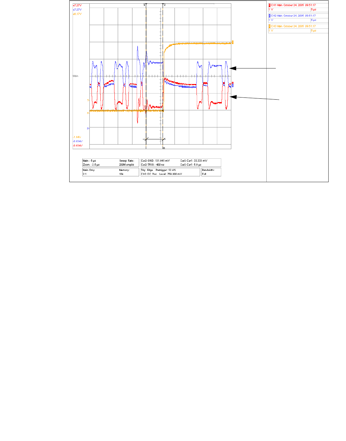
Fig. 2.7 - 1 CAN telegram with error frame
The Error Frame Counter switches, since one block of the CAN telegram (6 bits in this case) has
maintained the same state for approx.6µs. For a 1MBit bus, 1 bit has a length of 1µs, resulting in
a max. block length at the same level of 5µs.
The CAN Test Box Error Frame Counter is preset and counts 1 Mbit CAN bus at 5.5µs. 500KBaud
CAN bus HS60 is counted at 11µs.
These settings of 5.5µs and 11µs are factory set in the CAN Test Box with the help of a potenti-
ometer.
5.9µs
CAN _H level
CAN _L level

1 - 22
SIPLACE CAN Bus Edition 10/2018
22
Comments: