00194932-20 User Manual CAN Test Box-Error Frame Diagnostic unit_en.pdf - 第69页
1 - 69 Edition 10/2 018 SIPLACE CAN Bus 69 Axis unit version 04 with two connectors for t he CAN Bus ca ble, but there is only one machine CAN Bus cable from the machine, so we need th e additional CAN Bus cable to co nn…
1 - 68
SIPLACE CAN Bus Edition 10/2018
68
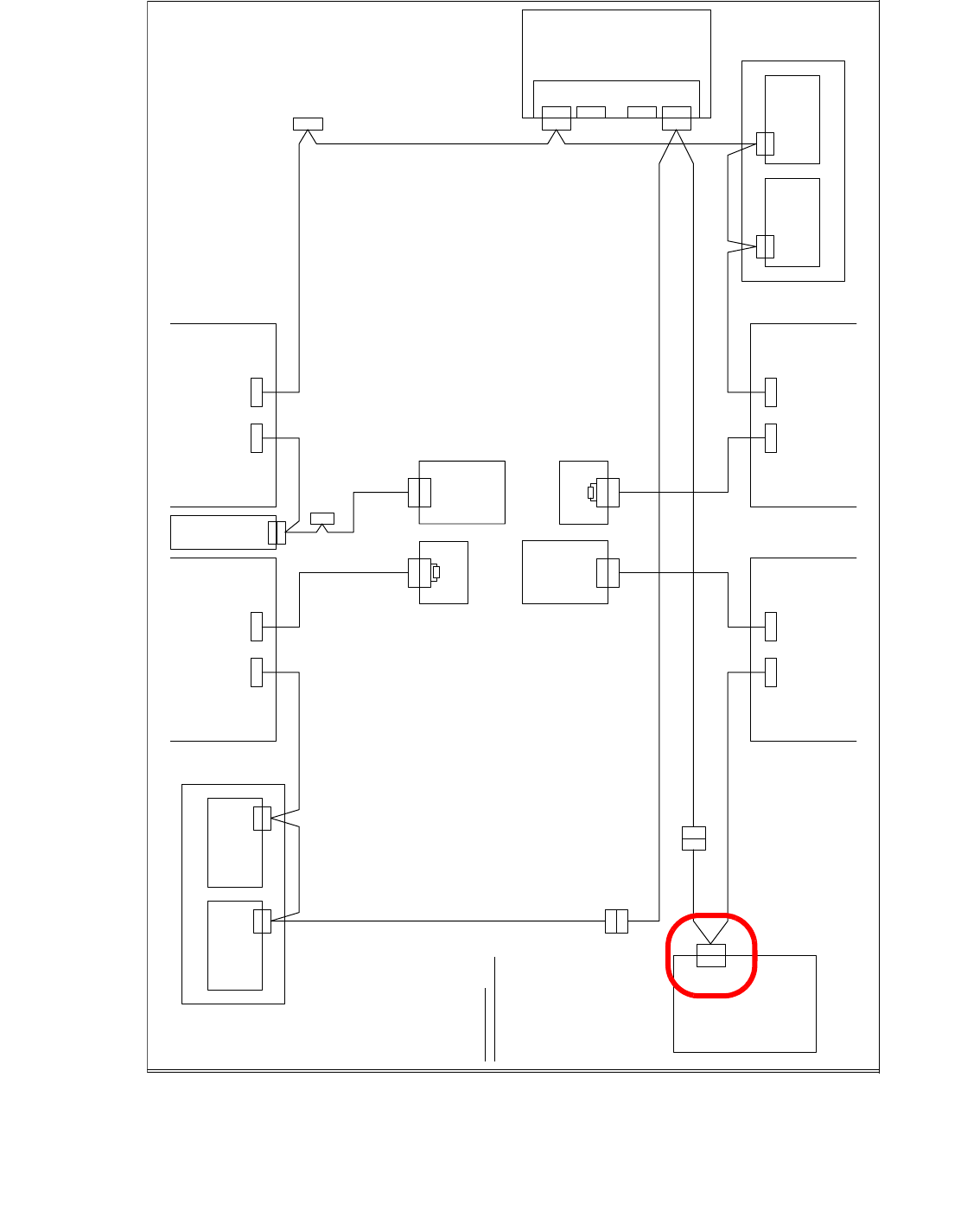
Axis Unit Version 03
V i s i o n C o n t r o l - U n i t
0 0 3 6 3 9 6 1 ( q d )
C A N
M a i n D i s t r i b u t o r
0 3 0 1 0 0 0 4 ( q a )
X 2 q d
X 2 q d
C A N
X 1 q b
X 1 q b
E i n z u g 2 E i n z u g 1
X 1 2 5X 1 2 6
C A N - I nC A N - O u t
X 1 1 5X 1 1 6
C A N - I nC A N - O u t
C A N
L P - S t e u e r u n g
X 2 2 a o
X 2 2 a o
C A N I / O - M o d u l
0 0 3 5 5 0 5 1 ( q b )
B u
S tB uS t
B uB u
0 3 0 1 0 0 5 0
B u
C A N
X 9 t q
0 3 0 1 0 0 5 1
B u
X 2 r d X 1 r b
X 1 4 5
C A N - I n
B u B u
B u
A x i s U n i t
0 3 0 1 6 1 1 0
X 9 s q
C A N
E i n z u g 3
X 1 3 6
C A N - O u t
X 4 0 c a
C A N
X 4 0 c a
0 3 0 1 0 0 5 7
S t
B u
X 2 r d
C A N
C A N I / O - M o d u l
0 0 3 5 5 0 5 1 ( r b )
X 1 r b
C A N
S u b D i s t r i b u t o r
0 3 0 1 0 0 0 5 ( r a )
V i s i o n C o n t r o l - U n i t
0 0 3 6 3 9 6 1 ( r d )
E i n z u g 4
S c h l e p p I n t e r f a c e
0 3 0 1 0 6 1 2
P 1
( c a )
S c h l e p p I n t e r f a c e
0 3 0 1 0 6 1 2
P 3
X 6 7
0 3 0 1 0 0 5 4
S t
C o m p u t e r U n i t
X 1 3 5 X 1 4 6
C A N - I n C A N - O u t
S t
B u
X 9 s q
B u
0 3 0 1 0 0 5 6
0 3 0 1 0 0 5 3
0 3 0 1 0 0 5 2
X 6 8
U m g e b u n g s d r u c k s e n s o r
P n e u m a t i k e i n h e i t
X 6 6
X 6 6
B u
B u S t
X 6 7
0 3 0 1 0 0 5 5
B e s t ü c k b e r e i c h 2 B e s t ü c k b e r e i c h 1
X 4 0 d a
B u
X 4 0 b a
B u
C A N - B u s A d e r b e l e g u n g
A d e r N r . B e l e g u n g S u b - D - P I N
1 " 1 - W i r e " 1
2 G N D 6
3 C A N _ L 2
4 C A N _ H 7
5 G N D 3
6 R E S E T 8
7 P o w e r F a i l 4
8 V C C ( 2
4 V ) 9
9 C A N _ I N T 5
( b a )
X 4 0 b a
X 4 0 b a
0 3 0 0 2 1 1 0
X 6 p n
X 6 p n
B u
K o m m u n i k a t i o n s b a u g r u p p e
X 7 p nX 1 2 p n
f r e if r e i
X 1 1 p n
X 1 1 p n
B u
C A N - B U S 1C A N - B U S 2
S t
1 2 0 O h m
A b s c h l u s s w i d e r s t a n d
0 3 0 2 7 6 4 6
X 1
X 1
S t
1 2 0 O h m
A b s c h l u s s w i d e r s t a n d
0 3 0 2 7 6 4 6
1 - 69
Edition 10/2018 SIPLACE CAN Bus
69
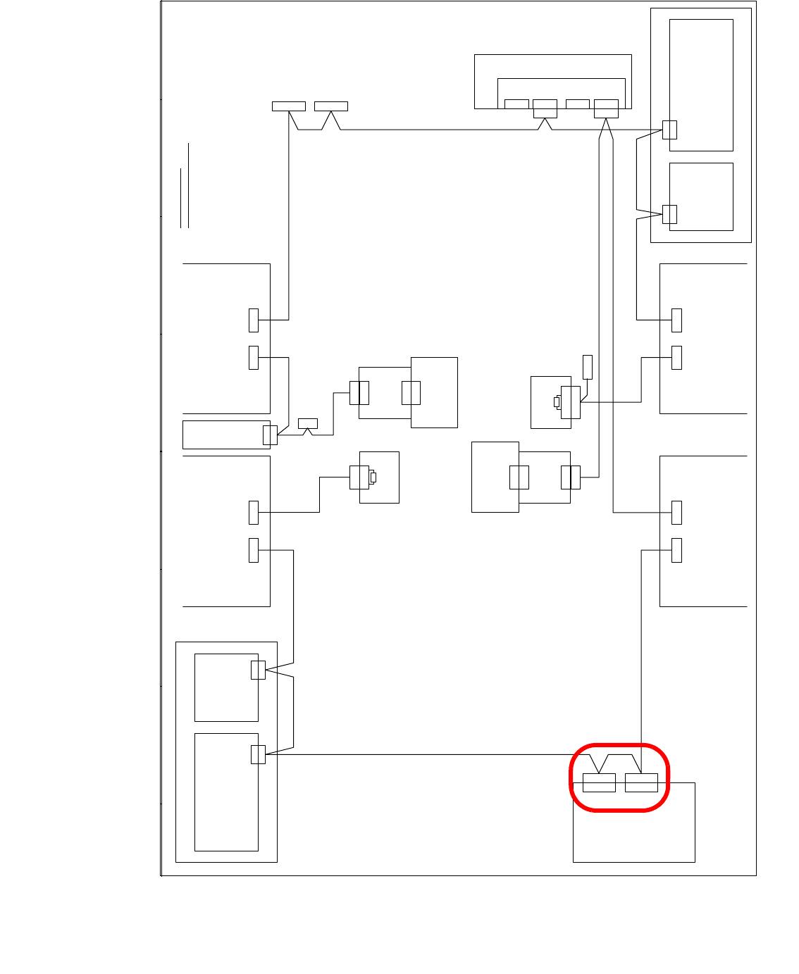
Axis unit version 04 with two connectors for the CAN Bus cable, but there is only one machine
CAN Bus cable from the machine, so we need the additional CAN Bus cable to connect the sec-
ond connector for the Axis unit version 04.
V i s i o n C o n t r o l - U n i t
0 0 3 6 3 9 6 1 ( q d )
C A N
M a i n D i s t r i b u t o r
0 3 0 1 0 0 0 4 ( q a )
X 2 q d
X 2 q d
E i n z u g 2 E i n z u g 1
X 1 2 5X 1 2 6
C A N - I nC A N - O u t
X 1 1 5X 1 1 6
C A N - I nC A N - O u t
C A N
L P - S t e u e r u n g
X 2 2 a o
X 2 2 a o
C A N I / O - M o d u l 0 0 3 5 5 0 5 1 ( q b )
B u
S tB uS t
B u
0 3 0 1 0 0 5 0
C A N
0 3 0 1 0 0 5 1
X 2 r d
X 1 4 5
C A N - I n
B uB u
A x i s U n i t
0 3 0 1 6 1 1 0
X 3 0 _ 2 s q
C A N
E i n z u g 3
X 1 3 6
C A N - O u t
X 4 0 c a
C A N
S t
X 2 r d
C A N
S u b D i s t r i b u t o r
0 3 0 1 0 0 0 5 ( r a )
V i s i o n C o n t r o l - U n i t
0 0 3 6 3 9 6 1 ( r d )
E i n z u g 4
( c a )
S c h l e p p I n t e r f a c e
0 3 0 1 0 6 1 2
P 3
0 3 0 1 0 0 5 4
C o m p u t e r U n i t
X 1 3 5
C A N - I n
B u
B u
X 6 8
U m g e b u n g s d r u c k s e n s o r
P n e u m a t i k e i n h e i t
B e s t ü c k b e r e i c h 2
B e s t ü c k b e r e i c h 1
C A N - B u s A d e r b e l e g u n g
A d e r N r . B e l e g u n g S u b - D - P I N
1 " 1 - W i r e " 1
2 G N D 6
3 C A N _ L 2
4 C A N _ H 7
5 G N D 3
6 R E S E T 8
7 P o w e r F a i l 4
8 f r e i 9
9 C A N _ I N T 5
C A N
X 3 0 _ 2 s q
X 3 0 _ 1 s q
B u
X 3 0 _ 1 s q
B u
X 3 0 _ 2 t q
B u
X 3 0 _ 1 t q
X 1 4 6
C A N - O u t
S t
C A N I / O - M o d u l 0 0 3 5 5 0 5 1 ( r b )
X 4 0 a a
( a a )
S c h l e p p I n t e r f a c e
0 3 0 1 0 6 1 2
P 1
0 3 0 1 0 0 5 9
X 4 0 c a
B u
X 4 0 b a
B u
0 3 0 1 0 0 5 3
B u
B u
X 4 0 a a
B u
B u
B u
X 1 r b
X 1 q b
0 3 0 0 2 1 1 0
X 6 p n
X 6 p n
K o m m u n i k a t i o n s b a u g r u p p e
X 7 p nX 1 2 p n
f r e if r e i
X 1 1 p n
X 1 1 p n
C A N - B U S 1C A N - B U S 2
S t
1 2 0 O h m
A b s c h l u s s w i d e r s t a n d
0 3 0 2 7 6 4 6
X 1
1 2 0 O h m
A b s c h l u s s w i d e r s t a n d
0 3 0 2 7 6 4 6
X 1
S t
0 3 0 1 0 0 5 2
X 3 0 _ 1 s q
B u
f r e i
X 2 h e
X 1 h e
1 - W i r e H u b
0 3 0 1 0 5 7 7 ( h e )
X 2 h e
X 1 h e
1 - W i r e H u b
0 3 0 1 0 5 7 7 ( h e )
X 4 0 d a
C A N
X 1 q b
C A N
X 1 r b
1 - 70
SIPLACE CAN Bus Edition 10/2018
70
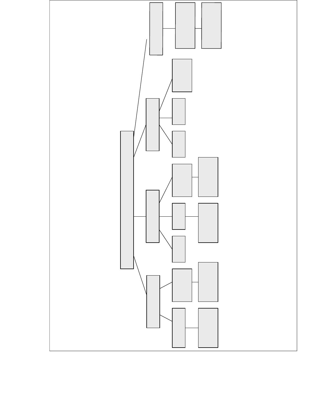
4.8 Overview of CAN Bus structures for X-series
X-serie
X2
X3 X4
Variant 1 Variant 2 Variant 1 Variant 2Only Variant 2
Variant 3
with CAN
Node
Variant 3 and
WPC 4
Variant 3 and
WPC 4
Variant 3
with CAN
Node
Variant 3
with CAN
Node
Variant 2 and
WPC 4
Variant 2 and
WPC 4
X
4
I
V
a
r
i
a
n
t
3
w
i
t
h
C
A
N
N
o
d
e
O
n
e
B
o
x
P
C
,
C
A
N
N
o
d
e
a
n
d
H
C
U
/
G
C
U