00194932-20 User Manual CAN Test Box-Error Frame Diagnostic unit_en.pdf - 第91页
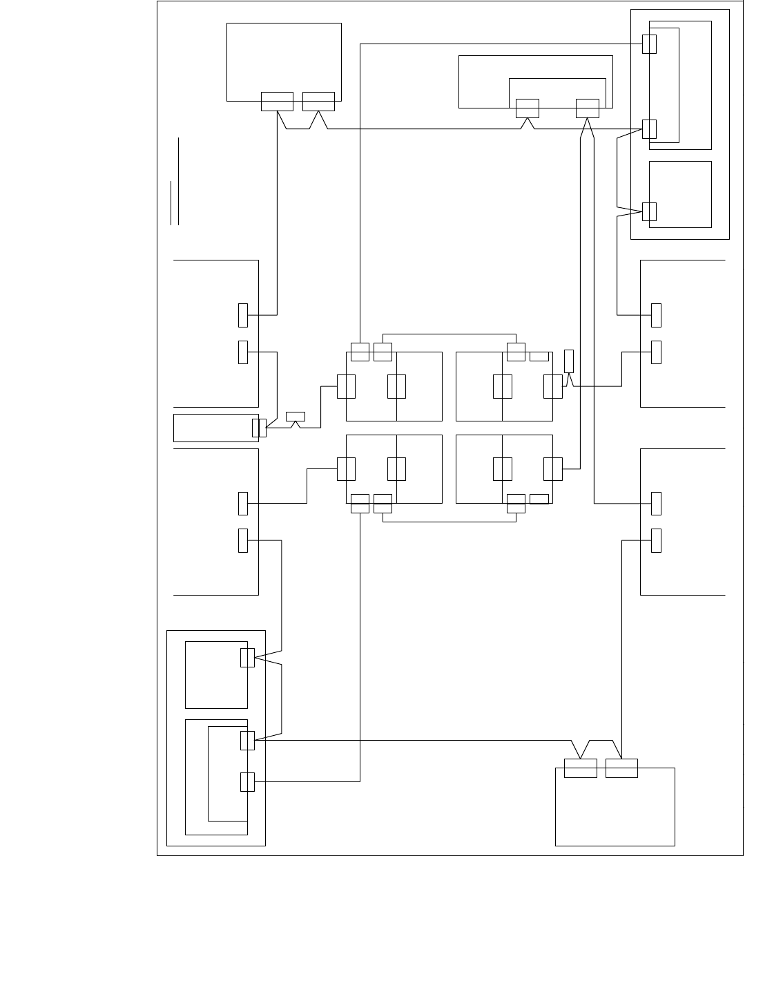
1 - 91 Edition 10/2 018 SIPLACE CAN Bus 91 Fig. 4.9 - 20 CAN Bus structure X4 variant 3 V i s i o n c o n t r o l 0 0 3 6 3 9 6 1 ( q d ) C A N X 2 q d X 2 q d D o c k i n g u n i t 2 D o c k i n g u n i t 1 X 1 2 5 X 1 …
1 - 90
SIPLACE CAN Bus Edition 10/2018
90
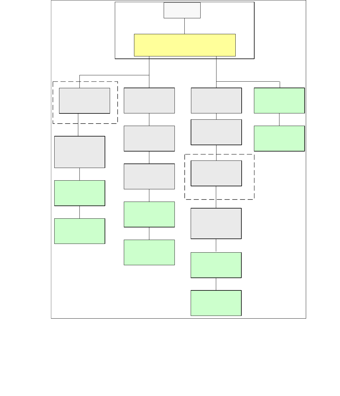
4.9.10 CAN Bus SIPLACE X4 (Variant 3)
Depending on the head configuration the subsystems MTC2 and stationary cameras (IC/FC) can
be installed. Maximum of two stationary cameras in each placement area can be installed.
Fig. 4.9 - 19 CAN Bus structure X4 variant 03
SMP BUS
MC
MC
Computer Unit
C
O
M
U
n
i
t
1
6
8
CAN Bus cable
PA 1
X6pn
Trailing Interface
Gantry 1
Transport
Control unit
COT 1 / CAN node
(Tape cutter, NC)
optional stat.
Camera vers.04)
Axis unit
PA 1
CAN I/O
Sub Module
SUB Distributor Sector 4
Trailing Interface
Gantry 4
Head board(C500)
Gantry 4
Terminator
(120 OHM)
Head board(C500)
Gantry 1
Terminator
(120 OHM)
CAN Bus cable
PA 2
X7pn
Main Distributor Sector 2
Axis unit
PA 2
CAN I/O
Main Module
COT 2 / MTC2
CAN node
(Tape cutter, NC)
(optional stat.
Camera vers.04)
Trailing Interface
Gantry 2
Trailing Interface
Gantry 3
Head board(C500)
Gantry 2
Terminator
(120 OHM)
Head board(C500)
Gantry 3
Terminator
(120 OHM)
COT 3 / CAN node
(Tape cutter, NC)
(optional stat.
Camera vers.04)
COT 4 / MTC2
CAN node
(Tape cutter, NC)
(optional stat.
Camera vers.04)
1 - 91
Edition 10/2018 SIPLACE CAN Bus
91
Fig. 4.9 - 20 CAN Bus structure X4 variant 3
V i s i o n c o n t r o l
0 0 3 6 3 9 6 1 ( q d )
C A N
X 2 q d
X 2 q d
D o c k i n g u n i t 2 D o c k i n g u n i t 1
X 1 2 5X 1 2 6
C A N I NC A N O U T
X 1 1 5X 1 1 6
C A N I NC A N O U T
C A N
P C B c o n t r o l
X 2 2 a o
X 2 2 a o
C A N I / O - m o d u l e 0 0 3 5 5 0 5 1 ( q b )
0 3 0 1 0 0 5 0
C A N
0 3 0 1 0 0 5 1
X 2 r d
X 1 4 5
C A N I N
S o
A x i s u n i t
0 3 0 5 0 3 6 5
X 3 0 _ 2 s q
C A N
D o c k i n g u n i t 3
X 1 3 6
C A N O U T
X 4 0 c a
C A N
X 2 r d
C A N
V i s i o n c o n t r o l
0 0 3 6 3 9 6 1 ( r d )
D o c k i n g u n i t 4
( c a )
C a b l e c a r r i e r i n t e r f a c e
0 3 0 1 0 6 1 2
P 3
0 3 0 1 0 0 5 4
X 1 3 5
C A N I N
X 6 8
A m b i e n t p r e s s u r e s e n s o r
P n e u m a t i c u n i t
P l a c e m e n t a r e a 2
P l a c e m e n t a r e a 1
C A N b u s w i r i n g
w i r e n o . w i r i n g S u b - D - P I N
1 " 1 - W i r e " 1
2 G N D 6
3 C A N _ L 2
4 C A N _ H 7
5 G N D 3
6 R E S E T 8
7 P o w e r F a i l 4
8 f r e e 9
9
C A N _ I N T 5
C A N
X 3 0 _ 2 s q
X 3 0 _ 1 s q
X 3 0 _ 1 s q
X 3 0 _ 2 t q X 3 0 _ 1 t q
X 1 4 6
C A N O U T
C A N I / O m o d u l e 0 0 3 5 5 0 5 1 ( r b )
X 4 0 a a
( a a )
C a b l e c a r r i e r i n t e r f a c e
0 3 0 1 0 6 1 2
P 1
0 3 0 1 0 0 5 9
X 4 0 c a
X 4 0 b a
0 3 0 1 0 0 5 3
X 4 0 a a
X 1 r b
X 1 q bX 6 q f
X 6 q f
C A N
X 2 q f
I n t e r f a c e 1 - W i r e C A T 5 ( q f )
0 3 0 4 1 5 7 8
M a i n d i s t r i b u t o r 0 3 0 4 6 2 2 5 ( q a )
X 6 r f
X 6 r f
X 1 2 p n X 1 1 p n
X 7 p n
C A N c a r d
X 6 p n
C A N b u s 1C A N b u s 2
C A N
0 3 0 4 1 5 7 8
I n t e r f a c e 1 - W i r e C A T 5 ( r f )
X 2 r f
S u b d i s t r i b u t o r 0 3 0 4 6 2 2 6 ( r a )
S o
S o
S o
S o
S o
S o
S oS o
S o S o
S o
S o P i nP i n
P i n P i nS oS o
S o
S o
M a c h i n e
c o n t r o l l e r
0 3 0 5 2 0 3 2
0 3 0 5 7 1 4 5
P a t c h c a b l e 5 m
X 1 f e
0 3 0 5 7 1 4 5
P a t c h c a b l e 5 m
C A N
2 / 3
X 3 0 _ 2 t q X 3 0 _ 1 t q
C A N
0 3 0 1 0 0 5 2
X 3 0 _ 1 s q
s p a r e
X 4 0 d a
C A N
( d a )
C a b l e c a r r i e r i n t e r f a c e
0 3 0 1 0 6 2 2
P 4
X 4 h e
C A N I n
X 5 h e
X 2 h eX 1 h e
1 - W i r e C A T 5 g a n t r y
0 3 0 4 2 2 1 4 ( f e )
C A N I n
X 5 f e
X 4 f e
X 2 f e X 1 f e
X 4 k e
C A N I n
X 4 0 d a
S o
X 5 k e
X 2 k e
X 1 k e X 2 k e
S w i t c h p o s . : t o p
X 2 f e
C A N
X 4 0 b a
( b a )
C a b l e c a r r i e r i n t e r f a c e
0 3 0 1 0 6 2 2
P 2
X 1 g eX 2 g e
1 - W i r e C A T 5 g a n t r y
0 3 0 4 2 2 1 4 ( g e )
S w i t c h p o s . : t o p
C A N I n
X 5 g e
X 4 g e
X 2 g eX 2 h e
0 3 0 4 2 3 4 7
1 - w i r e b r i d g e
1 - W i r e C A T 5 g a n t r y
0 3 0 4 2 2 1 4 ( h e )
S w i t c h p o s . : b o t t o m
1 - W i r e C A T 5 g a n t r y
0 3 0 4 2 2 1 4 ( k e )
S w i t c h p
o s . : b o t t o m
0 3 0 4 2 3 4 7
1 - w i r e b r i d g e
A x i s u n i t 1 / 4
0 3 0 5 0 3 6 5
X 1 h e
1 - 92
SIPLACE CAN Bus Edition 10/2018
92
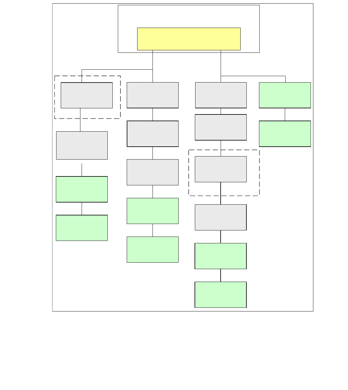
4.9.11 CAN Bus SIPLACE X4I with A364
For the SIPLACE X4I with stationssoftware 701, only one configuration depending on the subsys-
tems is possible. That means, the tape cutter and the nozzle changer will be control via the CAN
node and it is not possible to install an MTC2 or stationäry cameras. Therefore we have only the
CAN Bus structure which you can see below.
Fig. 4.9 - 21 CAN Bus structure X4I with A364
C
O
M
U
n
i
t
1
6
8
CAN Bus cable
PA 1
X6pn
Trailing Interface
Gantry 1
Transport
Control unit
COT 1
CAN node
(Tape cutter, NC)
Axis unit
PA 1
CAN I/O
Sub Module
SUB Distributor Sector 4
Trailing Interface
Gantry 4
Head board(C500)
Gantry 4
Terminator
(120 OHM)
Head board(C500)
Gantry 1
Terminator
(120 OHM)
CAN Bus cable
PA 2
X7pn
Main Distributor Sector 2
Axis unit
PA 2
CAN I/O
Main Module
COT 2
CAN node
(Tape cutter, NC)
Trailing Interface
Gantry 2
Trailing Interface
Gantry 3
Head board(C500)
Gantry 2
Terminator
(120 OHM)
Head board(C500)
Gantry 3
Terminator
(120 OHM)
COT 3
CAN node
(Tape cutter, NC)
COT 4
CAN node
(Tape cutter, NC)
Stationcomputer (Box PC)