00196062-03_SM_LDU-X_EN.pdf - 第11页
2 Overview 2.1 Purpose and Areas of Application Service Manual SIPLACE LDU-X Linear Dipping Unit 11/2017 11 2 Overview 2.1 Purpose and Areas of Application The SIPLACE placement machines have a special feeder module for …
1 Introduction
1.3 Staff Qualifications and Training
10 Service Manual SIPLACE LDU-X Linear Dipping Unit 11/2017
1.2.7 SIPLACE on the World Wide Web (WWW)
Log into our SIPLACE® homepage at http://www.siplace.com.
You can choose between the German and English versions.
The different sections contain information about our products, services and contact persons.
In addition, registered customers can also access the MySIPLACE user group. Here you can call
up special information about our placement systems, e.g.
●
technical documentation
●
technical information
●
spare parts lists etc.
Registration for theMySIPLACE user group is very simple:
► Click at the head of the web site on
and then on the Register
link.
► Fill in the registration form and send it off to us.
Soon afterwards, you will receive your access authorization with user name and password
1.3 Staff Qualifications and Training
Qualified or adequately trained personnel means that these people are familiar with the setting up,
operation and maintenance of the machine and the add-on devices and are suitably qualified, e.g.:
●
Have been trained, instructed or authorized to switch on and off, isolate, earth and identify
electrical circuits and system components in accordance with normal safety standards.
●
Have been trained or instructed in the upkeep and use of appropriate safety equipment in
accordance with normal safety standards.
●
Have received first aid training.
1.4 Abbreviations
CO Component
CP Collect&Place
C&P12 Collect&Place head with 12 segments
C&P20 Collect&Place head with 20 segments
C&P6 Collect&Place head with 6 segments
EDIF Energy and data interface
ESD Electrostatic sensitive device
Flat module Flat module plug-in board
FS Function status
IrDA Infrared Data Association
LDU Linear Dipping Unit
LED Light Emitting Diode
MTC Matrix Tray Changer
OIS Operator Information System
SSE Single Slot EDIF
SW Software
WPC Wafflepack changer

2 Overview
2.1 Purpose and Areas of Application
Service Manual SIPLACE LDU-X Linear Dipping Unit 11/2017 11
2 Overview
2.1 Purpose and Areas of Application
The SIPLACE placement machines have a special feeder module for supplying the flux in a suit-
able manner: the LDU‑X (Linear Dipping Unit). This LDU‑X can be set up and configured on a
changeover table in the same way as any other feeder module. The placement control software
(SIPLACE PRO) can be used to select components for dipping and to set the relevant parameters.
The LDU‑X makes the flux available in a certain area, in the pre-defined amount (layer thickness).
In addition, the LDU‑X performs an application run to automatically ensure that this layer of flux is
always renewed. This makes sure that the components are dipped in a fresh layer of flux and that
consistent process conditions are maintained.
2.2 Assembly and Function
The LDU‑X can be roughly divided into a mechanical section - an application unit - and an electrical
section - the so-called control unit.
The control unit
The control unit contains the electrical parts, such as the power supply, interfaces, the control sys-
tem and the operating unit.
The application unit
The application unit has two movement axes. The X axis moves a slide unit back and forth. The Z
axis moves the lift unit up and down. Both of these axes are driven by electrical motors and a
spindle system. A rotary encoder on the motor shaft determines the current position of the spindle.
Both axes have sensors which indicate when the axis reaches its end position.
The lift unit features a plate with a defined recess (cavity); the so-called dip plate. A tank, open at
the bottom, is fixed to the X-axis slide unit. The flux is located in this tank.
Procedure
The flux tank moves out of its park position, over the dip plate and leaves a predefined layer of flux
in the cavity. The slide unit moves to its reverse position and then back to the park position.
After this, the lift unit moves the dip plate upwards into the dipping position. The placement head
can then dip the component concerned into the layer of flux.
When it is time to renew the layer of flux, the lift unit moves down into the application position and
the slide unit moves the flux tank over the dip plate again.
Options
To optimize this procedure, the following auxiliary options are available.
●
Level sensor (flux level sensor)
The level sensor monitors the level of flux in the flux tank. If the required minimum level of flux
is undershot, the LDU-X is automatically stopped and the corresponding message displayed.
●
Refill unit
If the level sensor reports that the amount of flux in the flux tank is too low, the volume of flux
can be automatically refilled using the refill unit.
2 Overview
2.3 Application Process
12 Service Manual SIPLACE LDU-X Linear Dipping Unit 11/2017
2.3 Application Process
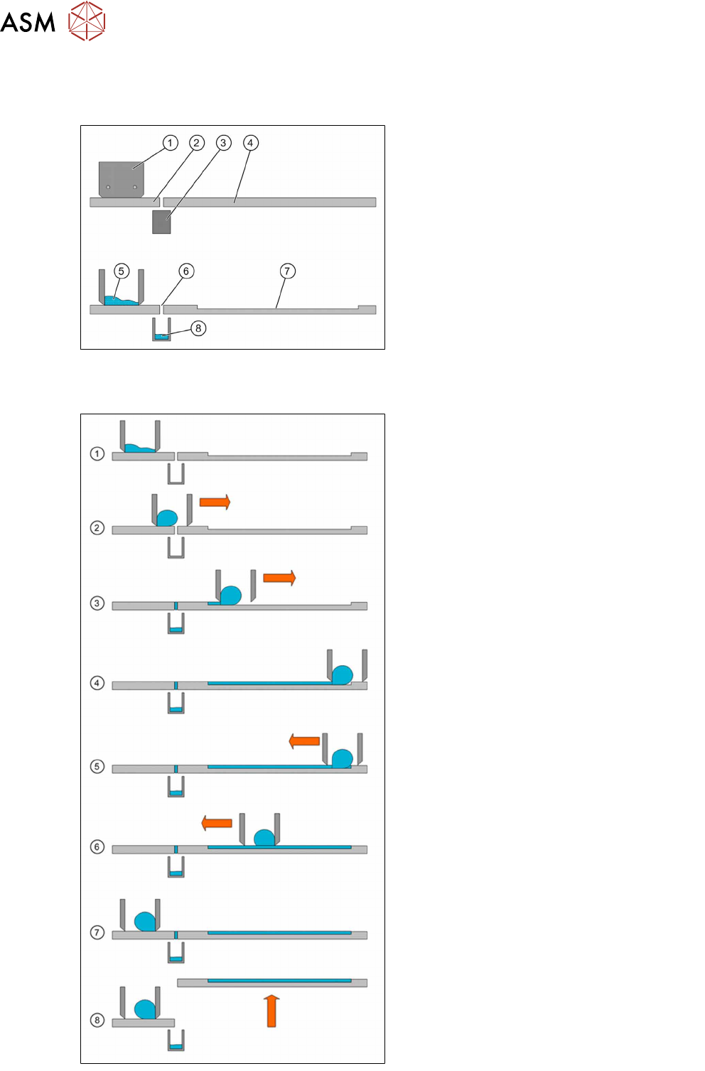
Application unit design
The LDU‑X application unit consists of the fol-
lowing main parts:
1. Flux tank
2. Park plate
3. Dip tray
4. Dip plate
5. Flux
6. Interface
7. Cavity
8. Flux in the dip tray
Application process
1. The application unit has been cleaned and
is now in its basic position. The flux tank is
over the park plate, in the park position.
The tank has been filled with new flux,
which is now spreading over the "base" of
the flux tank. The dip plate is in the applic-
ation position.
2. The application begins. The slide unit with
the flux tank moves forward in the direction
of the dip plate. The flux in the tank forms
a roll, depending on its viscosity.
3. The flux tank reaches the dip plate cavity.
The flux is distributed in the cavity and
wiped off by the bottom edge of the flux
tank.
4. The slide unit moves to its reverse position
at the end of the dip plate. The whole cav-
ity is now filled with flux.
5. The slide unit now moves back.
6. The flux roll now forms on the other side of
the flux tank. The edge strips off the layer
of flux applied to ensure that the flux layer
height remains constant.
7. The slide unit reaches the starting position
above the park plate. Any flux which may
have run into the gap in the interface area
will be caught by the dip tray.
8. The lift unit moves the dip plate out of the
application position and into the dip posi-
tion. The placement head can now dip the
components into the flux.