00196062-03_SM_LDU-X_EN.pdf - 第12页
2 Overview 2.3 Application Process 12 Service Manual SIPLACE LDU-X Linear Dipping Unit 11/2017 2.3 Application Process Application unit design The LDU‑X application unit consists of the fol- lowing main parts: 1. Flux ta…

2 Overview
2.1 Purpose and Areas of Application
Service Manual SIPLACE LDU-X Linear Dipping Unit 11/2017 11
2 Overview
2.1 Purpose and Areas of Application
The SIPLACE placement machines have a special feeder module for supplying the flux in a suit-
able manner: the LDU‑X (Linear Dipping Unit). This LDU‑X can be set up and configured on a
changeover table in the same way as any other feeder module. The placement control software
(SIPLACE PRO) can be used to select components for dipping and to set the relevant parameters.
The LDU‑X makes the flux available in a certain area, in the pre-defined amount (layer thickness).
In addition, the LDU‑X performs an application run to automatically ensure that this layer of flux is
always renewed. This makes sure that the components are dipped in a fresh layer of flux and that
consistent process conditions are maintained.
2.2 Assembly and Function
The LDU‑X can be roughly divided into a mechanical section - an application unit - and an electrical
section - the so-called control unit.
The control unit
The control unit contains the electrical parts, such as the power supply, interfaces, the control sys-
tem and the operating unit.
The application unit
The application unit has two movement axes. The X axis moves a slide unit back and forth. The Z
axis moves the lift unit up and down. Both of these axes are driven by electrical motors and a
spindle system. A rotary encoder on the motor shaft determines the current position of the spindle.
Both axes have sensors which indicate when the axis reaches its end position.
The lift unit features a plate with a defined recess (cavity); the so-called dip plate. A tank, open at
the bottom, is fixed to the X-axis slide unit. The flux is located in this tank.
Procedure
The flux tank moves out of its park position, over the dip plate and leaves a predefined layer of flux
in the cavity. The slide unit moves to its reverse position and then back to the park position.
After this, the lift unit moves the dip plate upwards into the dipping position. The placement head
can then dip the component concerned into the layer of flux.
When it is time to renew the layer of flux, the lift unit moves down into the application position and
the slide unit moves the flux tank over the dip plate again.
Options
To optimize this procedure, the following auxiliary options are available.
●
Level sensor (flux level sensor)
The level sensor monitors the level of flux in the flux tank. If the required minimum level of flux
is undershot, the LDU-X is automatically stopped and the corresponding message displayed.
●
Refill unit
If the level sensor reports that the amount of flux in the flux tank is too low, the volume of flux
can be automatically refilled using the refill unit.
2 Overview
2.3 Application Process
12 Service Manual SIPLACE LDU-X Linear Dipping Unit 11/2017
2.3 Application Process
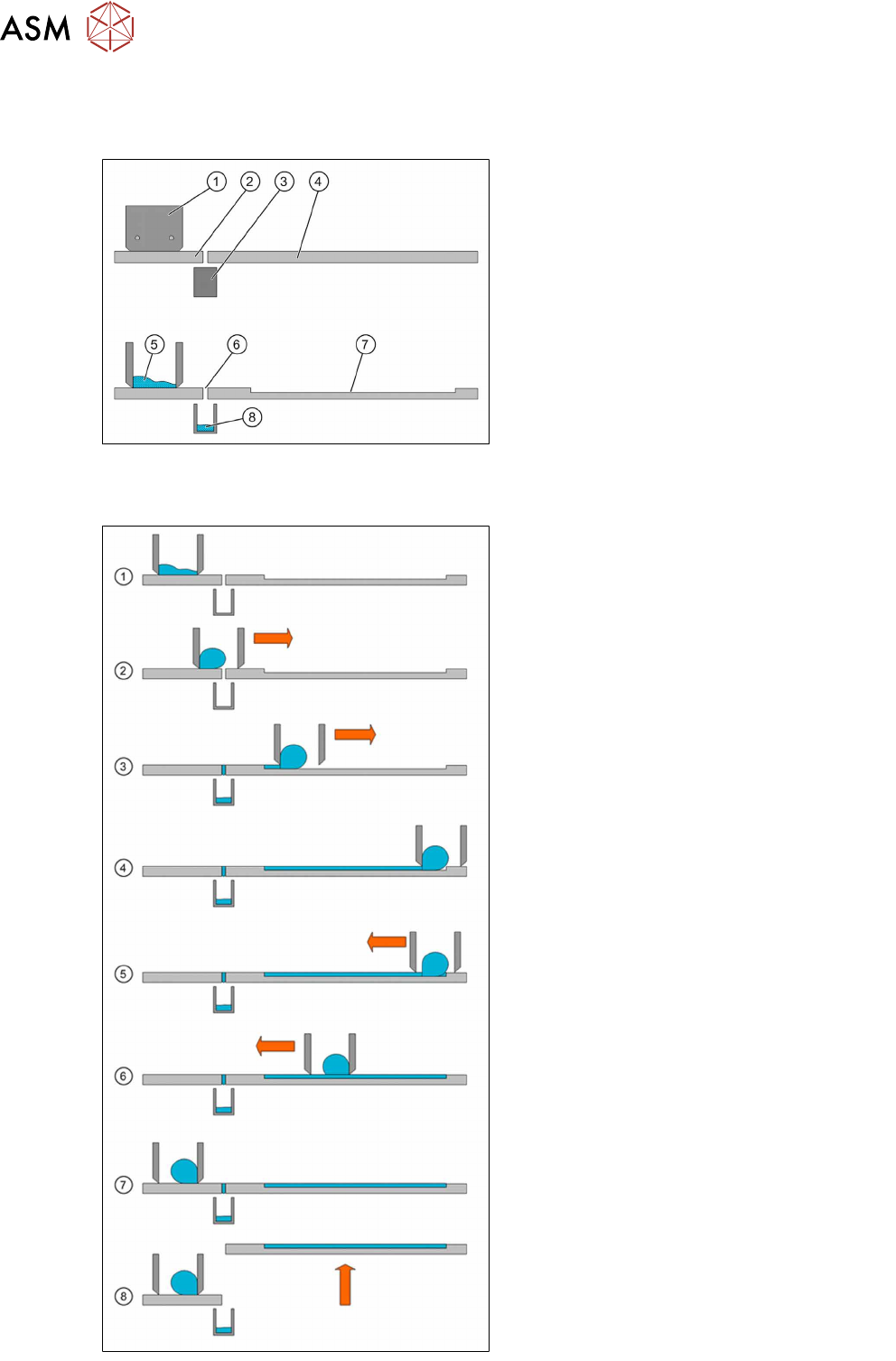
Application unit design
The LDU‑X application unit consists of the fol-
lowing main parts:
1. Flux tank
2. Park plate
3. Dip tray
4. Dip plate
5. Flux
6. Interface
7. Cavity
8. Flux in the dip tray
Application process
1. The application unit has been cleaned and
is now in its basic position. The flux tank is
over the park plate, in the park position.
The tank has been filled with new flux,
which is now spreading over the "base" of
the flux tank. The dip plate is in the applic-
ation position.
2. The application begins. The slide unit with
the flux tank moves forward in the direction
of the dip plate. The flux in the tank forms
a roll, depending on its viscosity.
3. The flux tank reaches the dip plate cavity.
The flux is distributed in the cavity and
wiped off by the bottom edge of the flux
tank.
4. The slide unit moves to its reverse position
at the end of the dip plate. The whole cav-
ity is now filled with flux.
5. The slide unit now moves back.
6. The flux roll now forms on the other side of
the flux tank. The edge strips off the layer
of flux applied to ensure that the flux layer
height remains constant.
7. The slide unit reaches the starting position
above the park plate. Any flux which may
have run into the gap in the interface area
will be caught by the dip tray.
8. The lift unit moves the dip plate out of the
application position and into the dip posi-
tion. The placement head can now dip the
components into the flux.

2 Overview
2.4 Requirements and restrictions
Service Manual SIPLACE LDU-X Linear Dipping Unit 11/2017 13
2.4 Requirements and restrictions
●
The LDU‑X can be used on SIPLACE X, SX and DX series machines.
●
The LDU‑X can only be set up on X tables. You can not configure the LDU-X on S tables.
●
The LDU-X can handle components up to a maximum size of 42x42 mm.
– X4i: If a WPC is used the maximum component size is 32x32 mm.
– SX1 and SX2: If the outer table position is used - depending on the head configuration -
there may be restrictions regarding the size of the components handled.
●
The LDU‑X requires station software version 604 or higher to operate on SIPLACE placement
machines.
●
The following restrictions are valid for the placement heads:
– SW 604 and 605: only C&P6, C&P12 and TwinHead
– from SW 703: no restrictions
●
The LDU‑X requires line computer software SIPLACE Pro version 5.0.1.35 and higher to op-
erate on SIPLACE placement machines.
●
The LDU‑X must be manually configured in the setup.
●
The LDU-X must not allocate the outer 6 tracks in each case (right and left).
●
You can only configure one LDU-X per table.
●
Do not set up any linear feeder modules directly next to the LDU-X.
●
Feeders with small components should not be set up directly next to the LDU-X.
●
The manual tray can not be set up on the same table as an LDU-X.
●
MTC and LDU-X units can only be set up opposite one another in single gantry machines.
●
The placement performance of the machine is limited by the dip process.
●
When dipping components, no placement data will be generated for operator information (OIS
or Ma-DaMaS).
●
A gantry can only operate with one LDU‑X (even if pickup can be performed from two place-
ment locations).
●
Only one LDU-X can be used for machines with one gantry in the placement area.
●
The LDU‑X can be operated outside the machine with the help of an SSE (Single Slot EDIF).
●
In case of SW 703 with SX there may be restrictions regarding the component size.
Hardware function status of LDU-X [03063461-xx]
Function
status
Explanation
FS1 The level sensor and refill unit can not be accommodated in this version.
FS2 In this version, the basic module is fitted 1.5 mm lower, to prevent the risk of
collisions between the level sensor and the placement head.
Software version 2.00 or higher is required to operate the level sensor.
FS3 The FS3 version has two additional sensors for detecting the dip plate and the
dip tray. This version is mandatory for the operation of the refill unit.
Software version 2.00 or higher is required for evaluation of the plate and tray
sensors, the level sensor and operation of the refill unit.