00196062-03_SM_LDU-X_EN.pdf - 第63页
4 Service Work 4.2 Replacing Spare Parts Service Manual SIPLACE LDU-X Linear Dipping Unit 11/2017 63 Description of terminal strip (11) In the terminal strip diagram, terminal K1 is located at the top, terminal K16 is at…
4 Service Work
4.2 Replacing Spare Parts
62 Service Manual SIPLACE LDU-X Linear Dipping Unit 11/2017
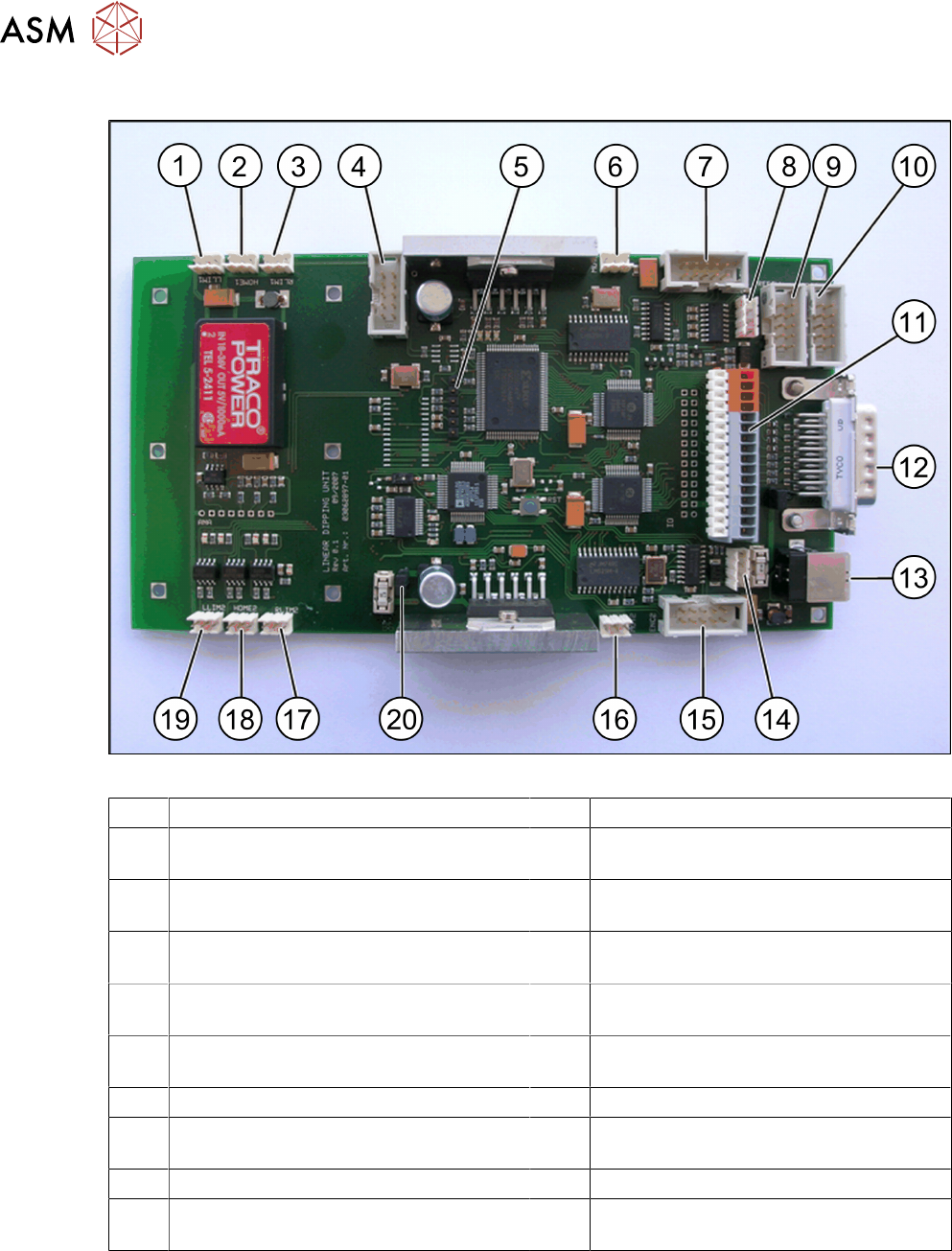
4.2.29.8 LDU-X Controller
Fig.4: LDU-X control board
1 3 pin connector strip for sensor (LLIM1) 2 From FS03 tray sensor
3 3 pin connector strip for sensor (RLIM1) 4 10 pin connector strip for refill unit
(MOT1)
5 6 pin connector pin strip for programming
interface
6 3 pin connector strip for motor, X axis
(MOT1)
7 10 pin connector strip for rotary encoder
from motor, X axis
8 4 pin connector strip for control board, X
adapter
9 10 pin connector strip for refill unit (op-
tional)
10 10 pin connector strip for service cable
(RS232)
11 16 pin terminal strip
(for details see table below)
12 Sub-D connector
13 USB socket 14 4 pin connector strip for display
15 10 pin connector strip for rotary encoder
from motor, X axis (MOT2)
16 3 pin connector strip for motor, X axis
(MOT2)
17 3 pin connector strip for sensor (RLIM2) 18 From FS03 dip plate sensor
19 3 pin connector strip for sensor (LLIM2) 20 2 pin connector strip for emergency stop
button
4 Service Work
4.2 Replacing Spare Parts
Service Manual SIPLACE LDU-X Linear Dipping Unit 11/2017 63
Description of terminal strip (11)
In the terminal strip diagram, terminal K1 is located at the top, terminal K16 is at the bottom.
K1 30V K9 -
K2 30V identification FS2 connection to K8 K10 -
K3 30V level sensor (+) brown K11 -
K4 30V key switch K12 Refill LED (+)
K5 Key switch K313 GND refill LED (-) blue
K6 Level sensor switch cable black K14 GND level sensor (-)
K7 - K15 GND
K8 Identification FS2 connection to K2 may
only be used with FS2
K16 GND
4.2.29.9 Assembling and Fitting the LDU Basis
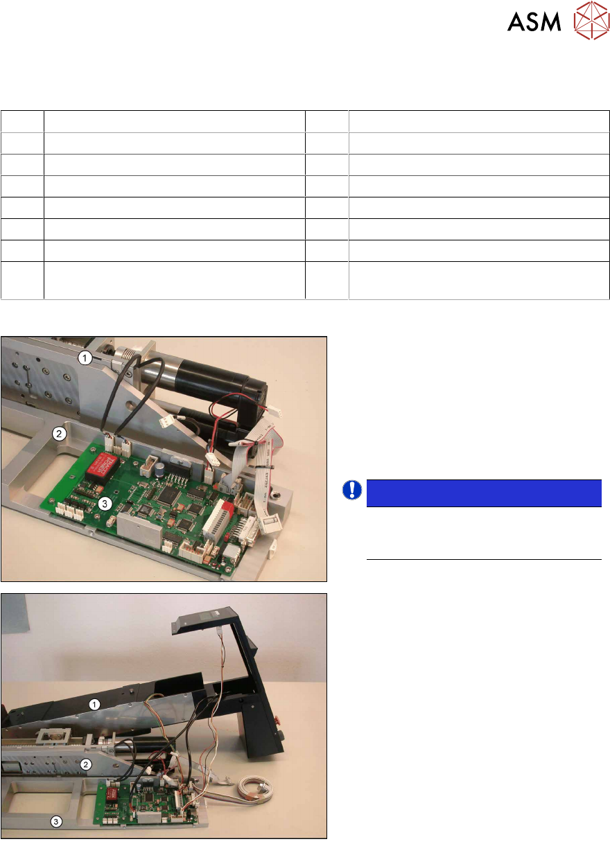
► Place the lower section of the base
unit(2) and the LDU-X control
board(3) and the upper section of the
base unit(1) next to one another, as
shown in the diagram.
► Restore all press-fit connections in the
rear part of the LDU-X control board,
which points to the upper section.
NOTICE!
For an overview of the LDU-X con-
trol board press-fit connections,
refer to the previous section.
.
► Place the LDU housing(1) with the
other parts, as shown in the dia-
gram(2) and(3).
► Restore all press-fit connections
between the housing and the LDU-X
control board (service and emergency
stop button, display, control board X
adapter).
4 Service Work
4.2 Replacing Spare Parts
64 Service Manual SIPLACE LDU-X Linear Dipping Unit 11/2017
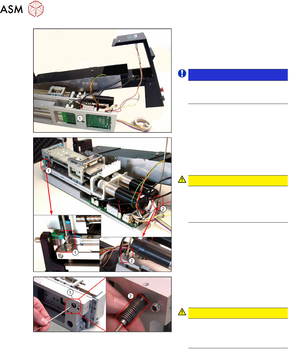
► Place the lower section of the base
unit(1) behind the upper section, as
shown in the diagram.
► Restore the other press-fit connec-
tions for the LDU-X control board.
NOTICE!
Check all press-fit connections.
These parts are not easy to reach
when everything has been fitted.
.
► Fit the upper and lower sections of the
base unit together. Make sure that the
rests for the two cup spring screws(1)
and(2) are still in the lower section of
the base unit.
CAUTION!
Running cables
Make sure that the cables can not
rub anywhere or block moving parts.
Take care that the cables are not
trapped or folded.
.
► Screw both parts together with the
two adjustment screws(1) and(2) .
► Reinsert the screw (1) fastening the
upper section of the LDU base unit
with the cup springs (2) and then
tighten.
CAUTION!
Cup springs
Make sure you have the correct num-
ber of cup springs (29 x). These must
be in pairs.
.