00196062-03_SM_LDU-X_EN.pdf - 第74页
4 Service Work 4.5 Errors 74 Service Manual SIPLACE LDU-X Linear Dipping Unit 11/2017 The following values will need to be reset after transferring the new firmware. ● Z zero position ● X zero position Adjusting the prod…
4 Service Work
4.4 Importing the LDU-X Firmware
Service Manual SIPLACE LDU-X Linear Dipping Unit 11/2017 73
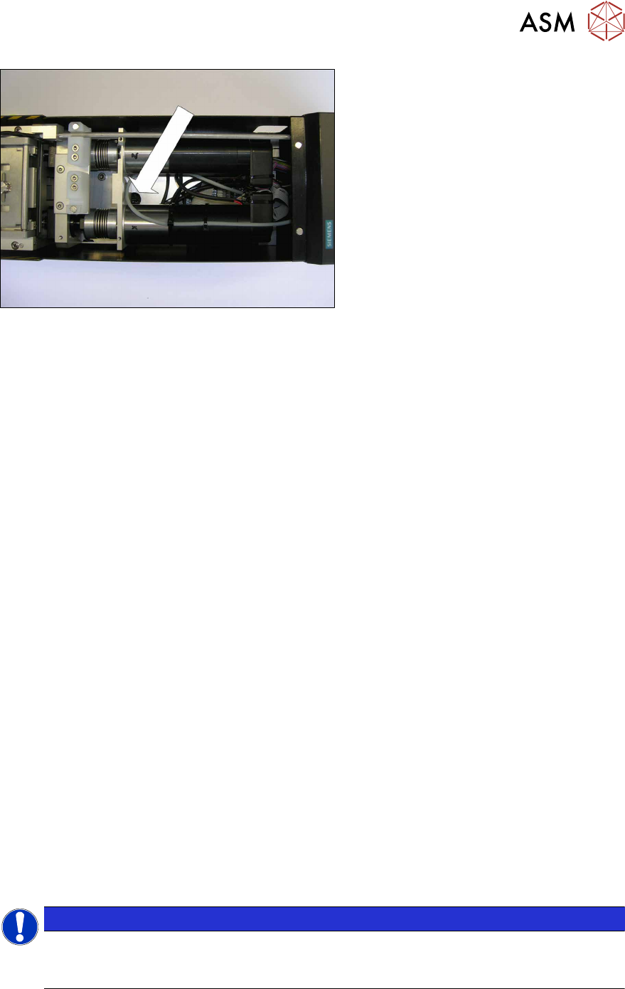
Only for function state 1 and 2. You do not
need to adjust the switch in function state
3.
► Remove the upper covers from the
LDU-X.
► You may need to remove the interme-
diate panel.
► Use a long, pointed object (screw-
driver) to adjust the switch. You may
find a flashlight helpful for locating it.
Transferring the LDU-X firmware
► Unlock the LDU-X from the changeover table if not done yet. This disconnects the LDU-X
from the voltage supply.
► For function status 1 and 2 only: Set the programming switch to position A (programming
mode)
► Connect the LDU-X service cable with the COM port of your PC.
► Start the WSD program.
► Push the LDU-X into the changeover table and lock into place.
The display will light up but no image will be shown at this stage.
If you are shown an image, this indicates that the programming switch has not switched over
properly.
► Click on the RESET button on the WSD user interface.
The - RESET OK message will be shown in the text box.
► Click on theDownload button on the WSD user interface.The data selection window will open.
► Navigate to the folder with the HEX file.
► Mark the HEX file.
► Click on the Open button.
Transfer of the LDU-X firmware will begin automatically. A progress bar will be shown. Wait
until the bar reaches the end and the process has finished.
The new LDU-X firmware has now been transferred.
► Unlock the LDU-X from the changeover table. This disconnects the LDU-X from the voltage
supply.
► Remove the service cable for the LDU-X from the COM port of your PC.
► For function status 1 and 2 only: Set the programming switch to position B (operating mode)
► Push the LDU-X onto the changeover table.
The display will light up and text will be shown.
► After switching on, initialization begins. The display shows the LDU-X firmware version. Check
whether the new version number is shown.
(Service menu / SYST INFORMATION / <VALUE -> / SOFTWARE: Vxxxxxxxxx)
NOTICE
Calibration of the LDU-X and adjustment of the production parameters is only required if the
Erase Mode is set to CODE AND DATA.
If the Erase Mode is set to CODE ONLY, the following steps are not required.
Calibrating the LDU-X
4 Service Work
4.5 Errors
74 Service Manual SIPLACE LDU-X Linear Dipping Unit 11/2017
The following values will need to be reset after transferring the new firmware.
●
Z zero position
●
X zero position
Adjusting the production parameters:
After transferring a new firmware, the production parameters are replaced with the default values.
See the parameters table for details: if you want to run the LDU-X with other parameters, you will
need to re-enter these.
●
Application speed
●
Language
●
Password, if required
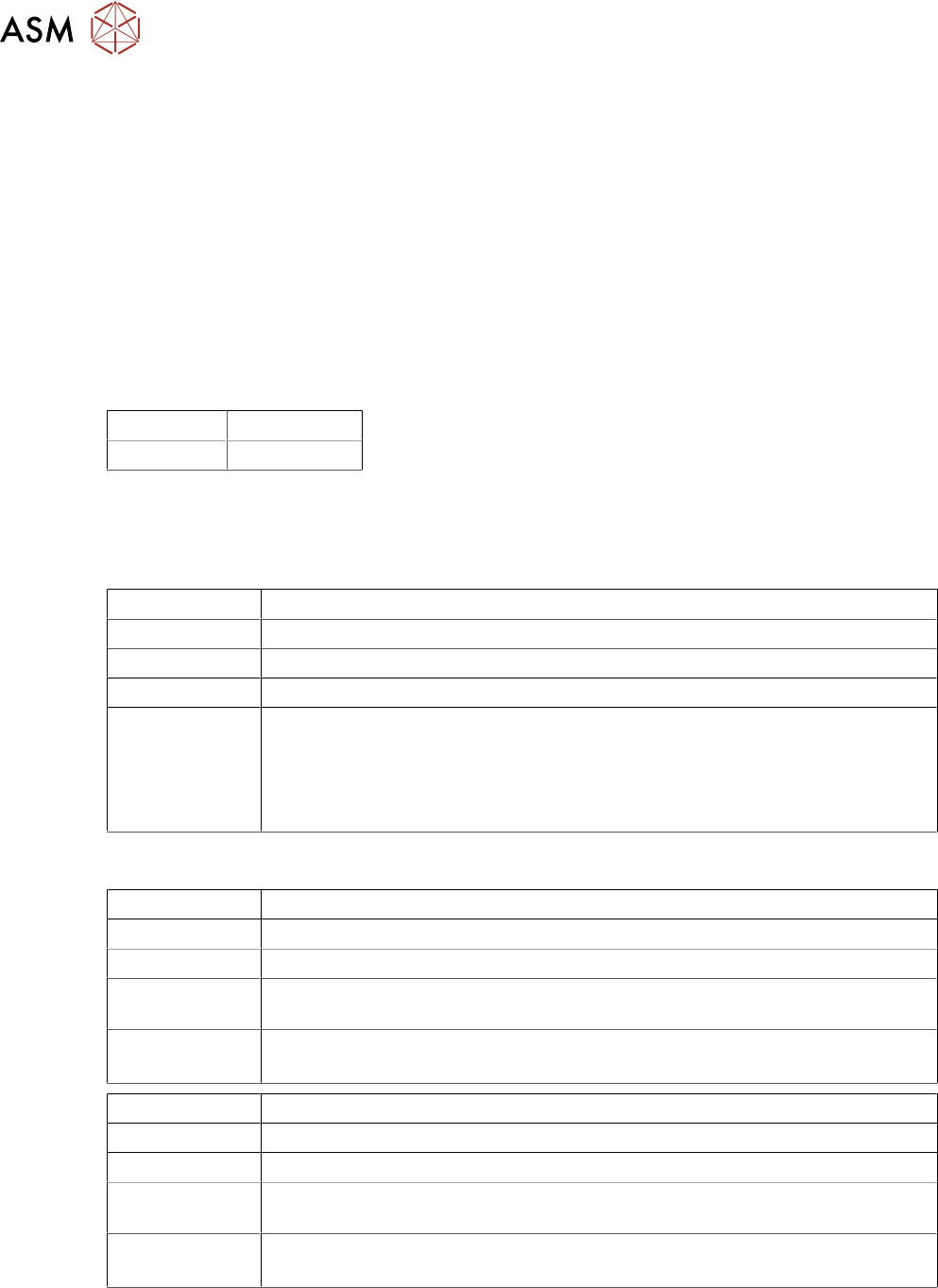
List of general parameters with default values
Language: English
Password: 1234
4.5 Errors
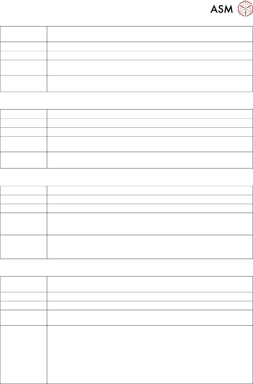
4.5.1 Unable to Communicate with the Placement Machine
Errors: The LDU-X shows no reaction during placement operations.
Display:
Status display: Red LED lights up
Cause: There is no communication between the LDU-X and the placement machine.
Solution: Check whether the LDU-X is in "S feeder mode":
Service menu / SYST INFORMATION / INTERFACE MODE X-TA
if not: change password with >ENTER
Check whether the LDU-X has been enabled in the station software for the
placement machine.
4.5.2 Leaking Flux
Errors: A significant amount of flux is leaking from the reverse position of the LDU-X.
Display: Normal
Status display: Normal
Cause: The flux tank is not sealed properly where it meets the plate. There may be un-
evenness, scratches, components on the plate or in the tank.
Solution: Check the zero position of the dip plate.
Check the contact pressure for the flux tank.
Errors: A significant amount of flux is leaking from the interface of the LDU-X.
Display: normal
Status display: normal
Cause: The flux tank is not sealed properly where it meets the plate. There may be un-
evenness, scratches, components on the plate or in the tank.
Solution: Check the zero position of the dip plate.
Check the contact pressure for the flux tank.
4 Service Work
4.5 Errors
Service Manual SIPLACE LDU-X Linear Dipping Unit 11/2017 75
Errors: A significant amount of flux is leaking from the dip plate, on the left and /or
right.
Display: normal
Status display: normal
Cause: The flux tank is not sealed properly where it meets the plate. There may be un-
evenness, scratches, components on the plate or in the tank.
Solution: Check the zero position of the dip plate.
Check the contact pressure for the flux tank.
4.5.3 Insufficient Flux Layer
Errors: A significant amount of flux is leaking from the reverse position of the LDU-X.
Display: normal
Status display: normal
Cause: The flux tank is not sealed properly where it meets the plate. There may be un-
evenness, scratches, components on the plate or in the tank.
Solution: Check the zero position of the dip plate.
Check the contact pressure for the flux tank.
4.5.4 Flux Tank Blocked
Errors: The flux tank collides with the dip plate (rubbing marks, sounds)
Display: Normal
Status display: Normal
Cause: The dip plate is not standing level with the home plate and forms a difference in
height as the interface. The flux tank scrapes over this "step" or hits in when
moving.
Solution: Check the Z height.
Check the gap at the interface.
Check whether there are contaminants (components) at the interface.
4.5.5 Initialization not Successful
Errors: The initialization run was not completed successfully. A significant amount of
flux is leaking from the reverse position of the LDU-X.
Display:
Status display: Red LED lights up
Cause: The flux tank is not sealed properly where it meets the plate. There may be un-
evenness, scratches, components on the plate or in the tank.
Solution: Check the sensors for the axes.
Check whether the switching flags for the axes still cover the sensors after the
initialization run.
Check the communication with the placement machine.
Check the USB port address.
Check whether the end position switch in the Z direction is reached during X
direction movement (green LED on the LDU control board). If needed, increase
the distance from the end position switch to the zero position.