00194550-0202_AI_Reject bin sensor_DE+EN.pdf - 第17页
Reject bin sensor 2 A ssembly instructions: Re ject bin sensor for the SIPLACE HF-series 08/2006 Edition 17 2 Assembly instructions: Reject bin sensor for the SIPLACE HF-series 2.1 Restrictions There is no possibility to…
1 Montageanleitung Abfrage Abwurfbehälter SIPLACE HF-Serie Abfrage Abwurfbehälter
Ausgabe 08/2006
16
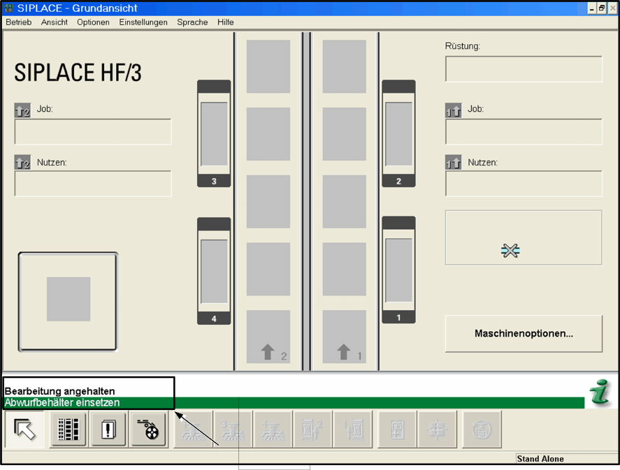
: Starten Sie die Maschine und prüfen Sie nacheinander durch Entnahme des jeweiligen Ab-
wurfbehälters die einwandfreie Funktion der Abfragesensoren.
Auf der Bedienoberfläche muss die Meldung „Abwurfbehälter einsetzen“ erscheinen.
1
1
: Vermessen Sie anschließend die Pipettenwechsler.
1
1
Reject bin sensor 2 Assembly instructions: Reject bin sensor for the SIPLACE HF-series
08/2006 Edition
17
2 Assembly instructions: Reject bin
sensor for the SIPLACE HF-series
2.1 Restrictions
There is no possibility to install the option for HF- and HF/3 machines built after 01.08.2005.
The cable described in chapter 2.10.1. doesn’t exist in these machines.
The reject bin sensor will be possible from SW 505.04 (end of 2006). 2
2.2 Parts required
2.2.1 Assembly kit
HF reject bin sensor (item no.: 00378293-01)
Qty Designation Part no.:
- 1 HF cable: reject bin 03006526-01
- 1 Scanning plate 03006260-01
- 1 Sensor mount 03021179-01
- 4 Screw DIN 912-M3 x 6-A2 00201463-01
- 4 Screw DIN 7981 - ST2.9 x 6.5-F-H-ST 00312271-01
- 6 Tallow-drop screw M3x10 DIN85/ISO PA 03005925-01
2.3 Tools required
– Set of hexagon socket spanners
– Set of screwdrivers
2
2
2
2

2 Assembly instructions: Reject bin sensor for the SIPLACE HF-series Reject bin sensor
08/2006 Edition
18
2.4 Safety instructions
WARNING
The safety instructions from the “Operational safety” chapter of the user manual and servicing in-
structions take precedence over these instructions. 2
The SIPLACE placement machines are supplied with mains voltage.
Consequently parts of these systems carry dangerous voltages! This voltage is present at certain
modules inside the machine base, even when the machine is switched off at the main power
switch.
Incorrect handling of the placement machine or touching live parts of the machine can result in
death or severe injury, and considerable damage to equipment.
BEFORE starting any work, shut down the operating system correctly, then switch the machine
OFF at the main power switch and disconnect from the main power supply. In addition, the com-
pressed air supply must be switched off at the compressed air unit's main valve in the machine
base and vented by actuating the needle valve on the compressed air unit.
There is DANGER for heart pacemaker wearers in the vicinity of the linear motors, as described
in detail in the "Special safety instructions for working in the vicinity of strong magnetic fields"
section of the user manual and service manual.
Always follow the accident prevention regulations, DIN or other standards and special safety
rules applicable in your country.
Pay attention to the information concerning residual voltages in the Operational Safety chapter.
Follow the ESD regulations as described in the operational safety section of the operating
instructions.
During the assembly, always secure the machine to prevent access by other people and to pre-
vent it being switched on again. The procedure is described in the “Locking the machine…” sec-
tion of the user manual.
Working with the SITEST program further increases the risk of accident.
The SITEST program must only be used by authorized and trained personnel.
2
2.4.1 Explanation of the symbols
2
2
2
Please note 2
2
2
2
Caution 2