00194550-0202_AI_Reject bin sensor_DE+EN.pdf - 第24页
2 Assembly instructions: Reject bin sensor for the SIPLACE HF-series Reject bin sensor 08/2006 Edition 24 2.10 Running the co nnecting cables : Run the two connecting cables in the cable duct behind the component docking…
Reject bin sensor 2 Assembly instructions: Reject bin sensor for the SIPLACE HF-series
08/2006 Edition
23
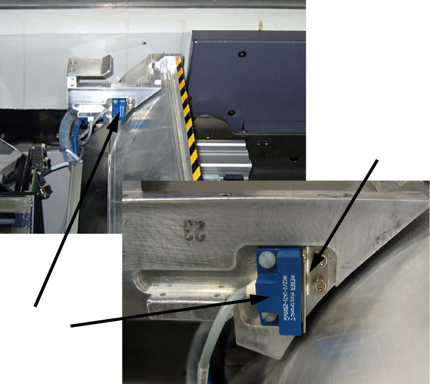
Fit the second sensor on the mount for the component reject bin in the park position
since only the large reject bin is installed in the TwinHead placement area. 2
To activate the sensor the scanning plate must be fitted using the enclosed hexagon socket head
screws. 2
2
2
2
2
2
2
2
2
2
Scanning plate
Sensor in
park position
2 Assembly instructions: Reject bin sensor for the SIPLACE HF-series Reject bin sensor
08/2006 Edition
24
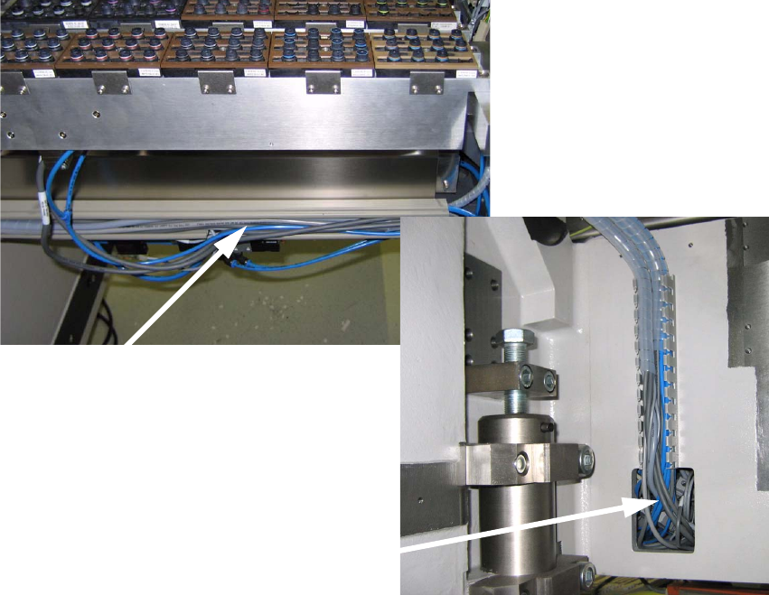
2.10 Running the connecting cables
: Run the two connecting cables in the cable duct behind the component docking unit and then
in the cable duct which leads to the opening in the machine frame.
2
2
Running the cables in the cable duct
Opening in the machine frame
Reject bin sensor 2 Assembly instructions: Reject bin sensor for the SIPLACE HF-series
08/2006 Edition
25
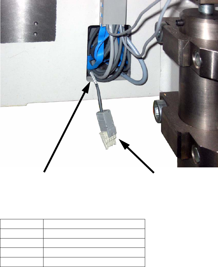
2.10.1 Connecting the cables
There is a corresponding cable to connect the sensors in the machine frame opening for evey lo-
cation. 2
2
2
Depending on the location the cable is labeled as follows: 2
2
2
2
2
2
Location Cable designation
1
03006733-01 (X11la) NO-523
2
03006735-01 (X11ma) NO-523
3
03006735-01 (X11na) NO-523
4
03006733-01 (X11oa) NO-523
Inscription label
Cable with plug for connecting the sensor