00194550-0202_AI_Reject bin sensor_DE+EN.pdf - 第26页
2 Assembly instructions: Reject bin sensor for the SIPLACE HF-series Reject bin sensor 08/2006 Edition 26 : Remove the connector with the cable link and con nect the se nsor cable instead. 2 2 2 Plug with cable link Cabl…
Reject bin sensor 2 Assembly instructions: Reject bin sensor for the SIPLACE HF-series
08/2006 Edition
25
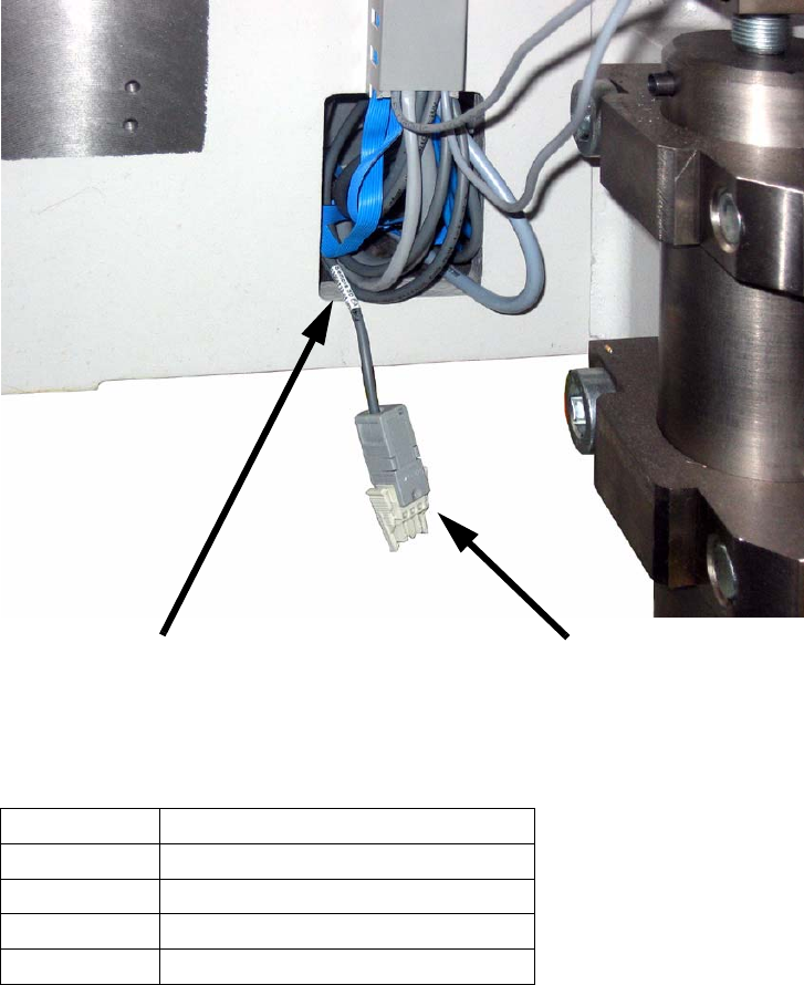
2.10.1 Connecting the cables
There is a corresponding cable to connect the sensors in the machine frame opening for evey lo-
cation. 2
2
2
Depending on the location the cable is labeled as follows: 2
2
2
2
2
2
Location Cable designation
1
03006733-01 (X11la) NO-523
2
03006735-01 (X11ma) NO-523
3
03006735-01 (X11na) NO-523
4
03006733-01 (X11oa) NO-523
Inscription label
Cable with plug for connecting the sensor
2 Assembly instructions: Reject bin sensor for the SIPLACE HF-series Reject bin sensor
08/2006 Edition
26
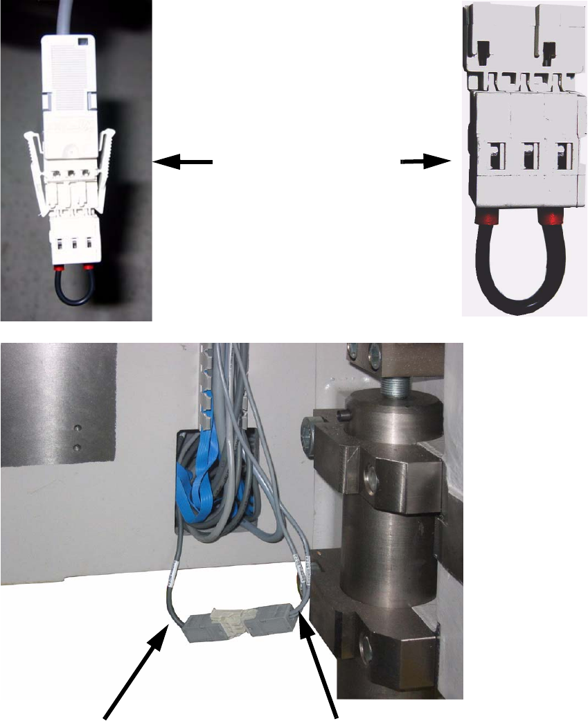
: Remove the connector with the cable link and connect the sensor cable instead.
2
2
2
Plug with cable link
Cable from the machine frame
Sensor cable
Reject bin sensor 2 Assembly instructions: Reject bin sensor for the SIPLACE HF-series
08/2006 Edition
27
2.10.2 Final tasks
: Fit the two connectors neatly in the machine frame and check, that all the cables are laid cor-
rectly so that they cannot be damaged (e.g. when docking in the component table).
2
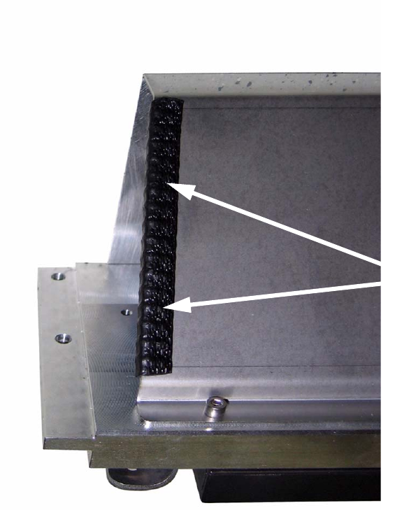
: If a second row of nozzle changer is installes, we recommend to isolate the edge of the pro-
tection sheet with an an adequate adhesive tape like shwn in the picture.
This avoids the damaging of the cable of the reject sensor.
2
2
: Fit the nozzle changer.
2
2
2
2
Edge protection