00193411-02.pdf - 第119页
User Manual SIPLAC E HS-60 5 O perator, Line engineer, Service engineer Software version SR.503.xx 07/2003 US Edition 5.8 Refilling components 119 5.8 Refilling component s The onl ine help con tains informat ion on re f…
5 Operator, Line engineer, Service engineer User Manual SIPLACE HS-60
5.7 Avoiding track errors Software version SR.503.xx07/2003 US Edition
118
5.7.4 Component coordinate system and pick-up angle
5
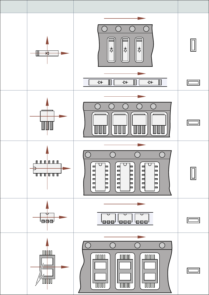
Fig. 5.7 - 2 Position of the component and its pick-up angle
Special
component
Stick
magazine:
Chip-
components
with polarity
0402
2220
The anode must be
aligned with the +X
coordinate.
Package
form type
Coordinate system
Position in the feeder
Pick-up angle
/
nozzle angle
Tape:
SOT23
Stick
magazine:
Tape:
Tape:
SO-IC
DIL-IC
SOT 194
Tape:
Holes
Y
X
Y
X
Y
X
Y
X
Y
X
90°
90°
0°
90°
-90°
0°

User Manual SIPLACE HS-60 5 Operator, Line engineer, Service engineer
Software version SR.503.xx 07/2003 US Edition 5.8 Refilling components
119
5.8 Refilling components
The online help contains information on refilling components with and without barcodes.
Æ With tape feeders, make sure that you always splice on a new tape early enough so that the
feeders do not run out of components.
Æ However, do not splice the tapes too early because if you wind the tape onto the new reel after
splicing the end of the old tape, the reel with the new tape may be overfilled. The tape could
then slip off the reel and become tangled. Under certain circumstances, this could cause pick-
up errors and prolonged down times.
Æ Always insert spindles when using tape reels of 5" and larger (see Fig. 5.4 - 3) and make sure
that the dividing plates are inserted correctly (see Fig. 5.4 - 3
).
5 Operator, Line engineer, Service engineer User Manual SIPLACE HS-60
5.9 Component trolley Software version SR.503.xx07/2003 US Edition
120
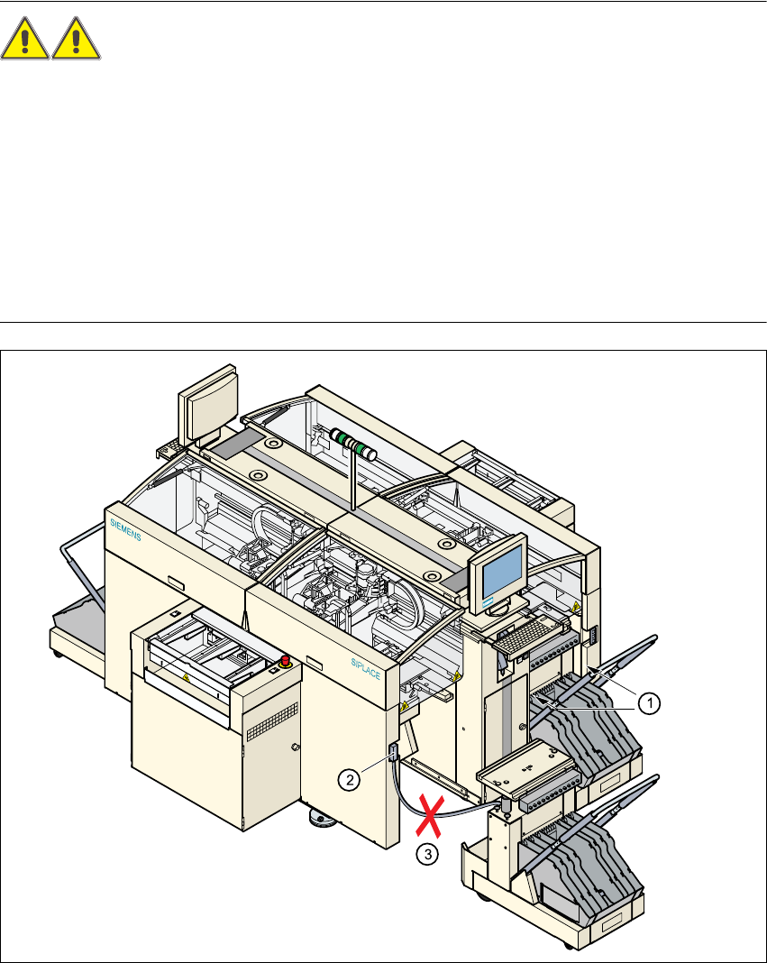
5.9 Component trolley
5.9.1 Safety instructions on docking and undocking the component trolley
WARNING 5
Æ Never reach into the gaps between the component trolley and the placement system while the
machine is running (see item 1).
Æ Always check that the component trolley is docked on the placement system before connecting
or disconnecting the connecting cable for the component trolley at the socket on the placement
system (item 2).
– Never connect the connecting cable for the component trolley to the socket on the placement
system and then operate the component trolley outside the machine via the compressed air
control unit (item 3).
5
Fig. 5.9 - 1 Safety instructions on the component trolley