00193411-02.pdf - 第142页
6 Component handling User Manual SIPLACE HS-60 6.4 Component trolley Software v ersion SR.503.xx 07/2003 US Edition 142 6 Fig. 6.4 - 3 Com pressed air supply for bulk case f eeders 6 (1) Compr essed ai r distrib utor (2)…

User Manual SIPLACE HS-60 6 Component handling
Software version SR.503.xx 07/2003 US Edition 6.4 Component trolley
141
6.4.3 External power supply for component trolley
To keep the time required for a setup change as short as possible, component trolleys can be set
up in advance at a special external location. The feeder functions and settings can be checked
there to prepare them for operation. We provide an external power supply for this purpose. It is
used to supply the component trolley with the required electrical power and compressed air.
Technical data
The kit contains a main power cable to European standards, a main power cable to US standards
and a connecting cable between the power supply and the component trolley.
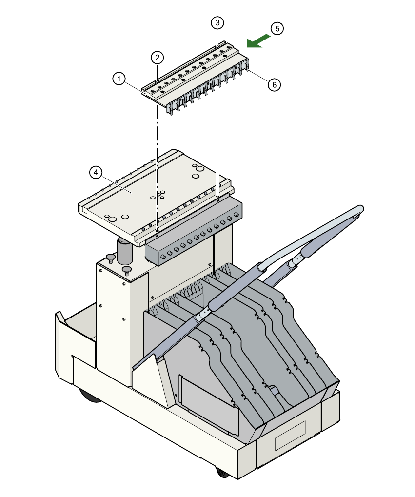
6.4.4 Compressed air supply for bulk case feeder
Bulk case feeders require compressed air to operate. We therefore offer a compressed air supply
for bulk case feeders as an optional extra.
It is easy to fit. The compressed air distributor (item 1) is fastened to the component table (item 4)
with two screws (items 2 and 3). The distributor is then connected to the compressed air supply
of the component trolley. The distributor has retaining clips (item 6) on the back. These secure the
bulk case feeder to the component trolley and ensure that the compressed air supply is working
properly.
Mains voltage 230 VAC ± 5 %
115 VAC ± 5 %
Compressed air connection Max. 1.0 MPa (10 bar)
Output pressure Can be regulated with a valve
6 Component handling User Manual SIPLACE HS-60
6.4 Component trolley Software version SR.503.xx 07/2003 US Edition
142
6
Fig. 6.4 - 3 Compressed air supply for bulk case feeders
6
(1) Compressed air distributor
(2) Screw DIN 912, M8x20
(3) Screw DIN 912, M5x10
(4) Component feeder table
User Manual SIPLACE HS-60 6 Component handling
Software version SR.503.xx 07/2003 US Edition 6.4 Component trolley
143
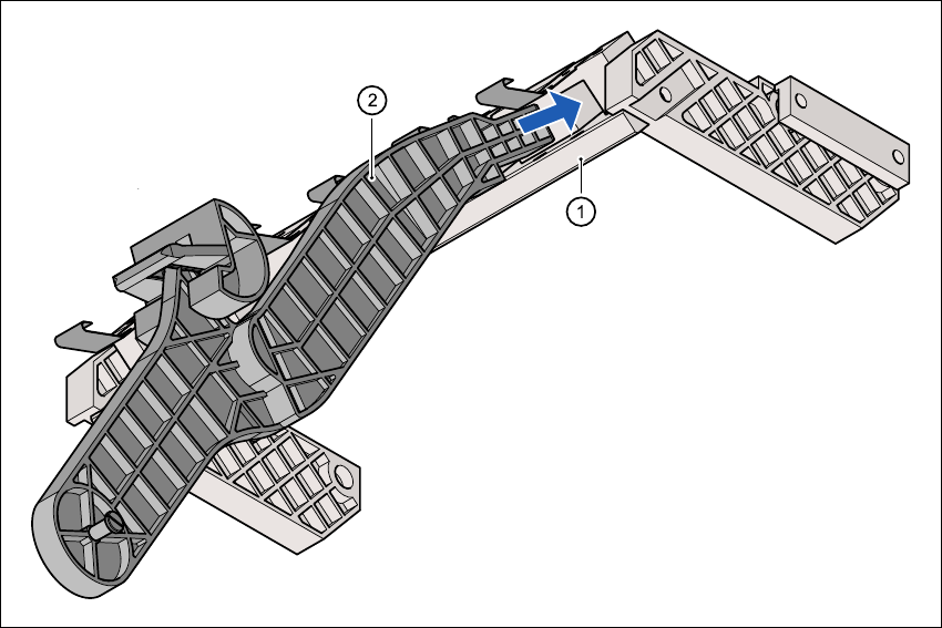
6.4.5 Support for the middle tape reel for 3 x 8 mm feeders
Type 3 x 8 mm S feeders transport components to the pick-up position on three tracks. The tape
reels for the two outer tracks are located between the dividing plates in the tape container. The
middle tape reel is arranged over the tape reels for the two outer tracks.
For the middle tape reels you will therefore also need:
– 1 adapter plate for holding the tape reel holder (item 1) and
– 1 tape reel holder (item 2) for every two feeders
The adapter plate is fixed to the component trolley with four fillister head screws, and the tape
reel holders are inserted into the square openings in the adapter plate.
Fig. 6.4 - 4 Support for the middle tape reel for 3 x 8 mm feeders
6
(1) Adapter plate
(2) Tape reel holder