00193411-02.pdf - 第165页
User Manual SIPLAC E HS-60 7 Station extensions Software version SR.503.xx 07/2003 US Edition 7.4 PCB barcode 165 7 * This valu e can onl y be achieved i f the barcode label on the PCB passes throu gh the scann er perpen…

7 Station extensions User Manual SIPLACE HS-60
7.4 PCB barcode Software version SR.503.xx 07/2003 US Edition
164
7.4.2 Description of the functions
7.4.2.1 PCB barcode reader for the single conveyor
The SIPLACE PCB barcode reader supports the flexible manufacture of SMD products, and in-
creases placement reliability. It recognizes all the code types conventionally used in industrial ap-
plications.
The laser scanner reads the barcode label on the topside or underside of each incoming PCB as
they are transported onto the input conveyor. The barcode data enables the line computer to au-
tomatically select the correct barcode allocation list from the previously created barcode assign-
ment list, and sends it to the station. If a barcode filter is defined, only information that is identified
as relevant within the barcode is compared. This procedure is carried out time neutrally during
placement of the PCB already in the machine. If several PCBs with the same barcode enter in
succession, the program is only transferred the first time. The following requirements apply to all
products to be produced using the PCB barcode:
– The component set-up must be identical on all the machines on the line
– All PCBs must be of the same width
7.4.2.2 PCB barcode reader for the dual conveyor
On the dual conveyor, the PCB barcode is only used to transfer the barcode via the GEM interface.
This is absolutely essential. The placement program cannot be supplied automatically.
7.4.3 Technical data
7
Max. component sizes for the single
conveyor
Standard: (L x W) up to 460 mm x 460 mm
Option: (L x W) up to 508 mm x 460 mm
(same width for all the jobs in a sequence)
Label dimensions Stroke width B: 0.19 < B ≤ 0.3 mm
(corresponds to high and medium density)
Stroke length: ≥ 4 mm*
Length of the barcode template window ≤ 90 mm
Label alignment on the PCB ** Parallel or perpendicular with respect to the PCB
transport direction, as close as possible to the sta-
tionary PCB transport side.
Label colors (contrast ratio > 70%
to DIN 66236)
Coding: black, dark green, dark blue
Background: white, beige, yellow, orange

User Manual SIPLACE HS-60 7 Station extensions
Software version SR.503.xx 07/2003 US Edition 7.4 PCB barcode
165
7
* This value can only be achieved if the barcode label on the PCB passes through the scanner
perpendicular to the machine’s transport direction.
** The position of the barcode reader on the input conveyor can be easily adjusted, depending
on where the barcode labels are located on the PCBs.
Code types Code 39, Code 128 / EAN 128,
Codabar, 2/5 IATA 2/5 industrial,
2/5 interleaved, UPC, EAN,
Pharma Code, EAN Addendum
(others available upon request)
Complete barcode Up to 25 digits (a barcode filter can also be defined)
Laser scanner safety Laser diode 670 nm (red) / 1.2 mW
Laser protection class 2, type of protection IP65
Station and line software Version 502.xx or later
Scanning / analysis duration Time neutral (T ≤ 1 s), since it is carried out in parallel
to placement of the previous PCB
7 Station extensions User Manual SIPLACE HS-60
7.4 PCB barcode Software version SR.503.xx 07/2003 US Edition
166
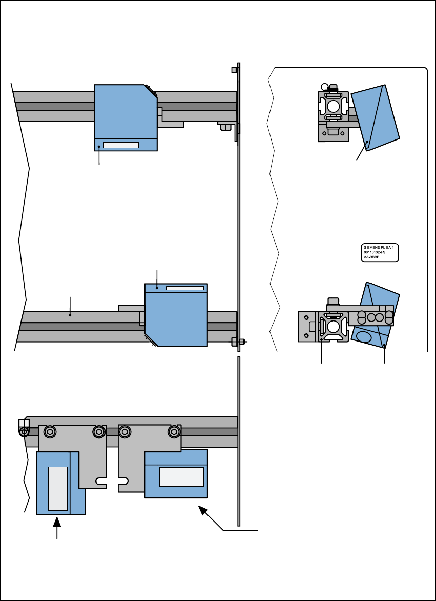
7.4.4 Assembly options for the PCB barcode reader
Fig. 7.4 - 3 Assembly options for the PCB barcode reader
Front view Side view
Assembly for
PCB barcode on
the PCB topside
Assembly for
PCB barcode on
the PCB underside
Plan view
Position of the PCB barcode reader
if the barcode strip is aligned parallel to
the PCB transport direction.
Position of the PCB barcode reader
if the barcode strip is aligned perpen-
dicular to the PCB transport direction.
Profiled rail
PCB barcode
reader 'topside'
PCB barcode
reader ‘underside’
Profiled rail