00193411-02.pdf - 第167页
User Manual SIPLAC E HS-60 7 Station extensions Software version SR.503.xx 07/2003 US Edition 7.5 Ceramic substrate centering 167 7.5 Ceramic substra te centering 7.5. 1 Gener al The ceram ic subs trate ca n be cente red…
7 Station extensions User Manual SIPLACE HS-60
7.4 PCB barcode Software version SR.503.xx 07/2003 US Edition
166
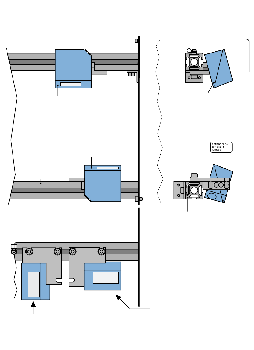
7.4.4 Assembly options for the PCB barcode reader
Fig. 7.4 - 3 Assembly options for the PCB barcode reader
Front view Side view
Assembly for
PCB barcode on
the PCB topside
Assembly for
PCB barcode on
the PCB underside
Plan view
Position of the PCB barcode reader
if the barcode strip is aligned parallel to
the PCB transport direction.
Position of the PCB barcode reader
if the barcode strip is aligned perpen-
dicular to the PCB transport direction.
Profiled rail
PCB barcode
reader 'topside'
PCB barcode
reader ‘underside’
Profiled rail

User Manual SIPLACE HS-60 7 Station extensions
Software version SR.503.xx 07/2003 US Edition 7.5 Ceramic substrate centering
167
7.5 Ceramic substrate centering
7.5.1 General
The ceramic substrate can be centered either mechanically or optically.
The position of the fiducials on the ceramic substrates can be detected either with
– the sub-gantry PCB camera with normal lighting that is fitted as standard, or
– using the multi-color PCB camera (option).
7
7.5.2 Mechanical centering
7.5.2.1 General
Mechanical substrate centering is used to lock ceramic substrates firmly in position in the X and
Y directions in such a way that the material is not damaged. Ceramic substrates can be placed
right up to the edge.
7.5.2.2 Assembling and dismantling the ceramic substrate centering unit
PLEASE NOTE
The ceramic substrate centering unit must only be assembled and dismantled by service engi-
neers. 7
7 Station extensions User Manual SIPLACE HS-60
7.5 Ceramic substrate centering Software version SR.503.xx 07/2003 US Edition
168
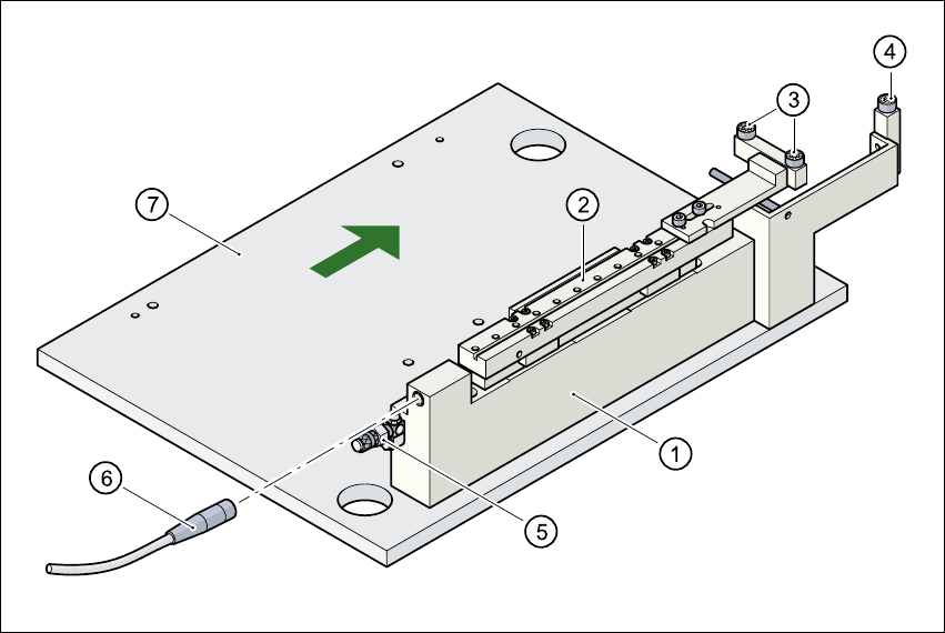
Fig. 7.5 - 1 Structure of the ceramic substrate centering unit
(1) Mechanical ceramic substrate centering
(2) Centering slide
(3) Ball bearing
(4) Stop
(5) Compressed air connection
(6) Proximity switch connecting cable
(7) Lifting table
7.5.2.3 Maintenance
– Make sure to clean and grease the ball bearings in the X axis centering unit.
– If necessary, check that the pneumatic driving mechanism is running smoothly.
– The conveyor should be maintained as described in the maintenance instructions.