00193411-02.pdf - 第177页
User Manual SIPLAC E HS-60 7 Station extensions Software version SR.503.xx 07/2003 US Edition 7.8 DCA camera 177 7.8 DCA cam era 7.8.1 Structure 7 Fig. 7.8 - 1 DCA camer a 7 (1) P CB camera, l ens and i lluminatio n (2) …

7 Station extensions User Manual SIPLACE HS-60
7.7 DCA camera on the 12-segment Collect&Place head Software version SR.503.xx 07/2003 US Edition
176
7.7.1 Description
With the DCA camera, the 12-segment Collect&Place head is able to optically center and place
components of the order of magnitude of 0.6 mm x 0.3 mm to 13mm x 13mm. The DCA package
optimizes the speed and accuracy when placing high-speed flip chips and bare die components.
7.7.2 Technical data
Component range 0201 to 13 mm x 13 mm
Component specification
Max. height
Min. lead pitch
Min. bump pitch
Min. ball/bump diameter
Min. dimensions
Max. dimensions
Max. weight
6 mm
0.4 mm
0.2 mm
0.11 mm
0.6 mm x 0.3 mm
13 mm x 13 mm
2 g
Z axis stroke Max. 16 mm
Programmable set-down force 2.4 to 5.0 N
Nozzle types 9 xx
Max. placement rate 15,000 comp/h
Angular accuracy ± 0.7° / 4 sigma
Placement accuracy of the DCA camera ± 75 µm / 4 sigma (gantry 4)
± 80 µm / 4 sigma (gantries 1-3)
User Manual SIPLACE HS-60 7 Station extensions
Software version SR.503.xx 07/2003 US Edition 7.8 DCA camera
177
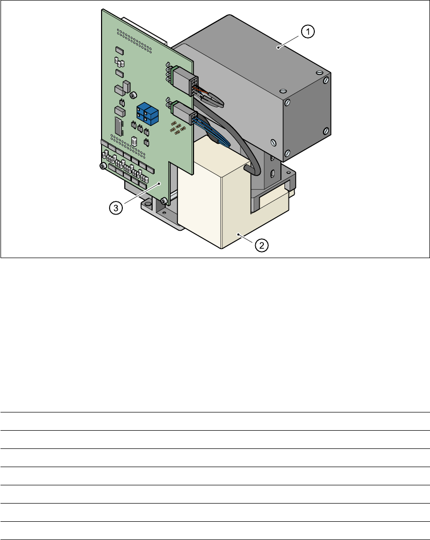
7.8 DCA camera
7.8.1 Structure
7
Fig. 7.8 - 1 DCA camera
7
(1) PCB camera, lens and illumination
(2) Camera amplifier
(3) Illumination control
7
7.8.2 Technical data
7
7
Component dimensions 0.6 mm x 0.3 mm to 13 mm x 13 mm
Component range 0201 up to 13 mm x 13 mm, flip-chip, bare die
Min. lead pitch 0.4 mm
Minimum bump pitch 0.2 mm
Min. ball/bump diameter 0.11 mm
Field of view 15.7 mm x 15.7 mm
Illumination method Front lighting (four levels programmable as required)
7 Station extensions User Manual SIPLACE HS-60
7.9 Component sensor Software version SR.503.xx 07/2003 US Edition
178
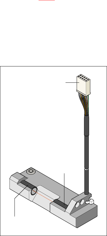
7.9 Component sensor
7.9.1 Function
The component sensor is fixed to the underside of the casing of the 12-segment Collect&Place
head (see Fig. 7.9 - 2
). It measures the height of the nozzle and the height of the nozzle with the
component. The component height is then determined from the two values. The sensor thus also
checks that the component is actually present.
Component heights from 0.1 to 4 mm can be checked. It is also possible to determine whether
the component is in its normal position or is sticking to the nozzle on edge. This requires the dif-
ference between the height and width of the component to be at least 100 µm, i.e. component
sizes 0603 or larger.
7
Fig. 7.9 - 1 Component sensor
To the ‘head gantry
distributor’ board
Infrared LED
Phototransistor
(receiver)