00193411-02.pdf - 第184页
7 Station extensions User Manual SIPLACE HS-60 7.10 SIPLACE pr oductivity lift Software version SR.503.xx 07/2003 US Edition 184 7.10. 4 T echnica l dat a 7 Supply v oltage 230/400 VAC, 110/230 VAC, ± 10%, 50/60 Hz Total…
User Manual SIPLACE HS-60 7 Station extensions
Software version SR.503.xx 07/2003 US Edition 7.10 SIPLACE productivity lift
183
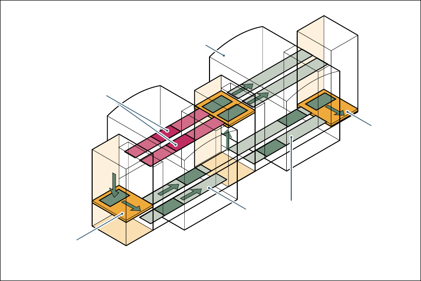
7.10.3 Advantages of the productivity lift
The productivity lift can raise the productivity of a line overall because it increases the placement
rates of the machines on the line.
7
Fig. 7.10 - 3 Productivity lift – avoiding stoppages
If lines are connected in parallel, individual machines may fail without bringing the entire line to a
standstill. It is also possible access individual machines while the rest of the line continues plac-
ing without interruption.
This could be for
– process-related investigations or test operation
– programming PCB fiducials, package forms or test placements
– maintenance or repairs
– operating errors, such as not splicing tapes on in good time or missing components.
Another advantage is that the line can be reconfigured as required using the software, without
having to reset the machines.
Conveyor section,
processing
Placement machine
Horizontal
and vertical lift
Underfloor conveyor
Track change

7 Station extensions User Manual SIPLACE HS-60
7.10 SIPLACE productivity lift Software version SR.503.xx 07/2003 US Edition
184
7.10.4 Technical data
7
Supply voltage 230/400 VAC, 110/230 VAC, ± 10%, 50/60 Hz
Total connected load 0.5 kVA
Total power 0.5 kW (2 A connected load)
Fuses 6.3 A
Power failure Max. 20 msec
Compressed air connection Min. 0.5 MPa (5.0 bar), 10 Nl/min
Length of the conveyor section 2385 mm
Length of the HV shuttle 540 mm
Width of the HV shuttle 1045 mm
Height of the HV shuttle 1200 mm (for conveyor height of 930 mm)
Weight of the HV shuttle 212 kg
Weight of the underfloor section 120 kg
Permissible load per unit area on foundation Min. 0.2 t/m²
Room temperature between 15 °C and 35 °C
Atmospheric humidity 30 - 70%, but no higher than 45% on average
in order to prevent any possibility of conden-
sation on the machine.
Max. noise generated 62 dBA
PCB conveyor height 930 ± 30 mm
PCB dimensions
Width
Length
Thickness
50 mm - 216 mm (2" – 8.5")
50 mm 460 mm (2" 18")
0.5 mm - 4.5 mm

User Manual SIPLACE HS-60 7 Station extensions
Software version SR.503.xx 07/2003 US Edition 7.11 Vacuum pump
185
7.11 Vacuum pump
Every Collect&Place head has a separate vacuum generator that supplies the holding and place-
ment circuit with the vacuum that it needs. The vacuum generator works on the Venturi principle.
The machine's compressed air consumption is approximately 950 Nl/min, which means that the
compressed air supply must be dimensioned accordingly. If the owner does not have sufficient ca-
pacity locally, the associated investment costs would be high, so we supply a vacuum pump that
will provide the necessary vacuum.
Other advantages of using the vacuum pump are:
– It roughly halves the machine's compressed air consumption.
– It reduces the input pressure.
– The placement machine can be easily integrated into existing lines.
– The ongoing operating costs reduce according to the energy costs.
The vacuum pump is maintenance-free and 100% oil-free. They have sufficient capacity to supply
the holding circuits of the Collect&Place heads.
Compressed air consumption
of the placement machine
Supply pressure of the
placement machine
Without vacuum pump 950 Nl/min.
0.65 MPa - 1.0 MPa
(6.5 bar - 10 bar)
With vacuum pump 400 Nl/min.
0.6 MPa - 1.0 MPa
(6.0 bar - 10 bar)