00193411-02.pdf - 第54页
2 Operational safety User Manual SIPLACE HS-60 2.5 Safety equipment Software version SR. 503.xx 07/2003 US Edition 54 2.5.4.2 S tructure of the si gnalling circuit The six si gnaling c ontacts for the cover s are co nnec…

User Manual SIPLACE HS-60 2 Operational safety
Software version SR.503.xx 07/2003 US Edition 2.5 Safety equipment
53
Push-button for raising and lowering the CO trolleys (item 2 in Fig. 2.5 - 6) 2
Use the push-buttons to raise and lower the component trolley table bed. To use this push-button,
and thus the drives for the component table you must first move the placement head out of the
range of the component feeder table and open the flap over the button. After changing the com-
ponent table, you must first close the flap over the button once again.
– If the flap is closed, the safety circuit contact will close and the signalling contact will open. The
machine is then ready for use.
– If the flap is open, the safety circuit is interrupted and the signalling contact closes. An error
message will appear on the screen prompting you to close the flap. The machine can then be
restarted using the Start button.
Uninterruptible power supply (UPS), station computer (item 3 in Fig. 2.5 - 6) 2
Both the UPS and the station computer are contained beneath the input conveyor.
WARNING
Always follow the safety instructions concerning potentially lethal voltages - even when the place-
ment system is switched off. 2
2.5.4 Safety circuit and signaling circuit
2.5.4.1 Structure of the safety circuit
The following contacts are connected in series and form the safety circuit loop :
– make contacts for the four protective cover switches
– make contacts for the two PCB conveyor covers
– make contacts for the two EMERGENCY-STOP buttons
– make contacts for the four component trolleys
– make contacts for the four flaps over the push-buttons for raising and lowering the CO trolleys
– channels 2 and 3 of the protective contactor combination PCC
If the safety loop is closed, 24 VDC is present at channels 2 and 3 of the PCC. The two green
LEDs for channels 2 and 3 light up in addition to the green Power ON LED. 2
2 Operational safety User Manual SIPLACE HS-60
2.5 Safety equipment Software version SR.503.xx 07/2003 US Edition
54
2.5.4.2 Structure of the signalling circuit
The six signaling contacts for the covers are connected in parallel and form the "cover signal" cir-
cuit. If one or more covers are opened, the contacts close, and the 24 V signal reaches the CAN
bus and signals that one of the covers is open.
The two signaling contacts for the EMERGENCY STOP buttons are connected in parallel and form
the "emergency stop push-button signal circuit". When an EMERGENCY-STOP button is pressed,
a 24 V signal is sent to the CAN bus and signals that one of the EMERGENCY-STOP buttons has
been pressed.
The four signalling contacts for the push-button flaps are connected in parallel. They form the
"Flap signal" circuit. If one or more flaps is raised, a 24 V signal is applied to the CAN bus and
signals that one of the cover flaps is not closed.
The four signalling contacts for the CO trolleys are connected in series and form the "Component
table" signal loop. If a CO trolley is missing, a 0 V signal is sent to the CAN bus. If all trolleys are
connected, the signal is approximately 16 V.
2.5.4.3 Description of the functions of the safety circuit
The following conditions must be fulfilled before the placement system can be started or operated:
– all four component trolleys must be docked in and connected.
– all covers - four over the gantries, one over the PCB input belt and one over the output belt -
must be closed.
– both EMERGENCY-STOP buttons must be released.
– all four flaps over the push-buttons for raising and lowering the CO trolley must be closed.
– the minimum operating pressure must have been reached.
– the software Enable signal must have been given, thus activating the safety circuit.
– The power supply must be sending 24 V to the start buttons and the protective contactor com-
bination.
– If one of the start buttons is now pressed, the protective contactor combination PCC will switch
and activate the following components:
– 200 V link voltage for the servo amplifiers for the gantry axes
– 100 V link voltage for the star axes
– Operating voltage for the lifting table motors
– the servo unit will receive a "Servo Enable" signal for the servo amplifier.
– 34 V operating voltage is switched to the CO trolleys
– 24 V operating voltage is switched to the used tape cutters.
The machine is then ready for use.
User Manual SIPLACE HS-60 2 Operational safety
Software version SR.503.xx 07/2003 US Edition 2.5 Safety equipment
55
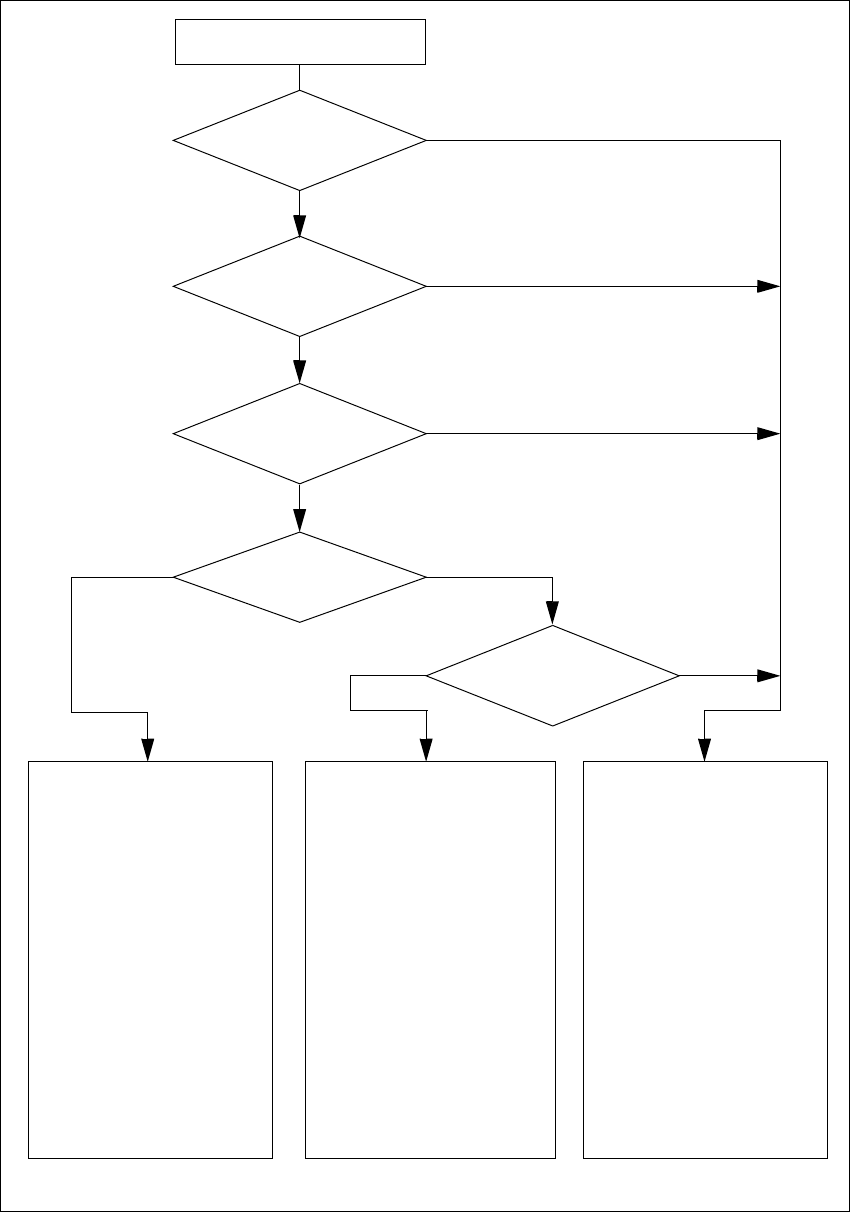
2
Fig. 2.5 - 7 Safety circuits
2
Compressed air
min. 0.65 MPa (6.5 bar)?
No
2
Start button pressed
2
EMERGENCY STOP
button pressed?
2
Protective cover open ?
2
Key switch
closed (position I)?
No
2
Component table
safety circuit interrupted?
Yes
No
No
Yes
Yes
No
2
Active
PCC*) Yes
Voltage
Y axis 200 V
X axis 200 V
Star axis 100 V
DP axis 30 V
Z axis 30 V
Active
PCB conveyor Yes
Lifting table Yes
PCB clamping Yes
Width adjustment Yes
Laser light barrier Yes
Used tape cutter Yes
Yes
2
Active
PCC*) No
Voltage
Y axis 0 V
X axis 0 V
Star axis 10 V
DP axis 30 V
Z axis 30 V
Active
PCB conveyor Yes
Lifting table No
PCB clamping No
Width adjustment Yes
Laser light barrier No
Used tape cutter No
2
Active
PCC*) No
Voltage
Y axis 0 V
X axis 0 V
Star axis 10 V
DP axis 30 V
Z axis 30 V
Active
PCB conveyor No
Lifting table No
PCB clamping No
Width adjustment No
Laser light barrier No
Used tape cutter No
2
*) PCC protective contactor combination
Yes