00193411-02.pdf - 第66页
2 Operational safety User Manual SIPLACE HS-60 2.9 Lock o ut and tag out procedur e Software version SR. 503.xx 07/2003 US Edition 66 2.9 Lock out and t ag out proced ure 2.9.1 Purpose and scope Before per forming any pr…
User Manual SIPLACE HS-60 2 Operational safety
Software version SR.503.xx 07/2003 US Edition 2.8 Energy state of the machine after switching off at the main power switch
65
2
2.8.2 Placement system switched off at the main power switch and disconnected ...
The automatic placement system is unpowered, apart from slight residual voltages in the servo
unit.
2.8.3 Compressed air conditions in the machine after switching off at the main
power switch
When the system is switched off at the main power switch (item 1 in Fig. 2.8 - 1) or if the power
supply fails, the electrically-controlled main valve Y1 of the compressed air unit closes (item 3 in
Fig. 2.8 - 1
, page ). The pressure will drop to 0 MPa (0 bar) within 5 seconds.
S1 main power switch
Terminals 1, 3, 5 3 x 204 VAC
3 x 230 VAC
3 x 380 VAC
3 x 400 VAC
3 x 415 VAC
Servo unit (see item 5 in Fig. 2.8 - 2
)
Test socket X2
Test socket X3
Test socket X4
GND X1
< 10 VDC
< 10 VDC
< 10 VDC
Control unit (see items 3, 4, 5, and 6 in Fig. 2.8 - 2
)
Test socket + 12 VDC (x3ta)
Test socket 12 VDC (x4ta)
Test socket + 15 VDC (x3tb)
Test socket -15 VDC (x4tb)
Test socket + 5 VDC (x3td)
Test socket + 24 VDC (x4td)
Test socket + 52 VDC (x5te)
Test socket + 5 VDC (x4te)
GND (x3td)
0 VDC
0 VDC
0 VDC
0 VDC
0 VDC
0 VDC
0 VDC
0 VDC
Module Voltage

2 Operational safety User Manual SIPLACE HS-60
2.9 Lock out and tag out procedure Software version SR.503.xx 07/2003 US Edition
66
2.9 Lock out and tag out procedure
2.9.1 Purpose and scope
Before performing any preventive maintenance work or service work, a procedure of locking and
tagging must be followed. The procedure, when followed correctly eliminates the possibility of an
employee being injured.
PLEASE NOTE
These procedures represent the minimum lock/tag out requirements. Any additional safeguards
needed to complete work safely can be specified by facilities supervision, the safety officer, the
safety committee and the health department. 2
2.9.2 Description
Whenever it becomes necessary to isolate, control and release energy, the following procedure is
to be followed
(1) Notify affected employees.
(2) Shut down the equipment. Carry out all normal stopping procedures, such as
– depressing the stop button,
– shutting down the station computer,
– switching off the placement system at the main switch.
(3) Isolate the machine from all its energy sources such as
– compressed air supply and
– power supply.
(4) Lock out the machine.
– Attach a lock whenever possible, e.g. to the motor contactor.
User Manual SIPLACE HS-60 2 Operational safety
Software version SR.503.xx 07/2003 US Edition 2.9 Lock out and tag out procedure
67
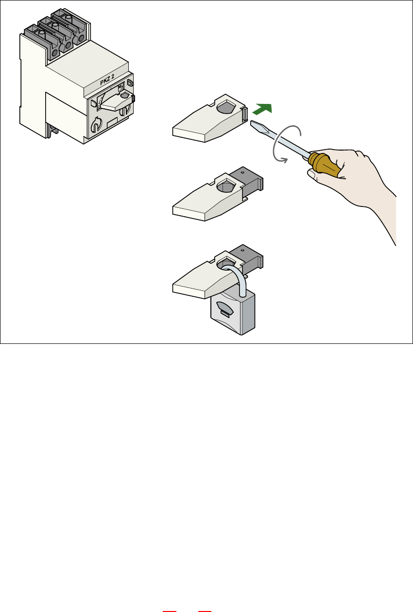
2
Fig. 2.9 - 1 Locking the motor contactor
2
(1) Turn the operating lever counter-clockwise.
(2) Use the screwdriver to push the locking lug out of the operating lever.
(3) Secure the operating lever with a padlock.
– The tag out alternative:
If a machine can be locked out, it must be. However, there are situations where energy iso-
lating devices cannot accommodate locks. In these cases, the energy isolating devices
must be tagged to warn employees that the machine is de-energized for servicing. The tag
must be securely fastened, it must be placed in a position visible to all and it may only be
removed by the person who attached it. 2
(4) Release stored energy
Stored energy in the compressed air supply or electrical energy in electrolytic capacitors must
be released by appropriate means. 2
– After switching off the placement machine wait until the voltages and the compressed air
have discharged (see Sections 2.6
and 2.7), to be able work without any risk.