00193411-02.pdf - 第73页
User Manual SIPLAC E HS-60 3 Technical data Software vers ion SR.503.xx 07/2003 US Edit ion 3.1 Descript ion of the machine 73 3 T echnical dat a 3.1 Description of the machine The auto matic pla cement sys tem is a high…
2 Operational safety User Manual SIPLACE HS-60
2.10 ESD guidelines Software version SR.503.xx 07/2003 US Edition
72
User Manual SIPLACE HS-60 3 Technical data
Software version SR.503.xx 07/2003 US Edition 3.1 Description of the machine
73
3 Technical data
3.1 Description of the machine
The automatic placement system is a high-performance placement system with four gantry axis
system. A PCB vision module and a star-shaped 12-segment Collect&Place-head are mounted
on each gantry. Collect&place heads equipped with a component vision module pick up the com-
ponents (CO) from stationary feeder modules and insert them into the PCB clamped in the PCB
conveyor.
3
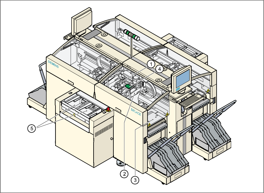
Fig. 3.1 - 1 Overall view of the placement system
(1)12-segment Collect& Place head with component vision module
(2)Gantry axis system with PCB vision module
(3)Stationary component feeding
(4)Clamped printed circuit board (PCB)
(5)PCB conveyor (dual conveyor option)
3 Technical data User Manual SIPLACE HS-60
3.1 Description of the machine Software version SR.503.xx 07/2003 US Edition
74
The concept behind the automatic placement system
– with its stationary feeder modules,
– PCBs that do not move during placement
– and positionable placement heads
has a number of significant benefits:
– With stationary feeder modules, even the tiniest components are picked up reliably.
– The components cannot slip on the PCB during placement (as is often the case with moving
PCBs) since the PCB does not move.
– Sophisticated optical centering systems (vision modules) for components and PCBs also en-
sure high component positioning accuracy.
– Components can be topped up and tapes can be spliced without stopping the machine.
– Prepared component trolleys enable the placement system to be retooled without long stop-
pages.