00193411-02.pdf - 第74页
3 Technical data User Manual SIPLACE HS-60 3.1 Description of the m achine Software v ersion SR.503.xx 07/2003 US Edition 74 The concep t behin d the autom atic pla cement sy stem – with i ts stationary f eeder modules, …
User Manual SIPLACE HS-60 3 Technical data
Software version SR.503.xx 07/2003 US Edition 3.1 Description of the machine
73
3 Technical data
3.1 Description of the machine
The automatic placement system is a high-performance placement system with four gantry axis
system. A PCB vision module and a star-shaped 12-segment Collect&Place-head are mounted
on each gantry. Collect&place heads equipped with a component vision module pick up the com-
ponents (CO) from stationary feeder modules and insert them into the PCB clamped in the PCB
conveyor.
3
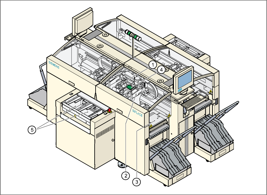
Fig. 3.1 - 1 Overall view of the placement system
(1)12-segment Collect& Place head with component vision module
(2)Gantry axis system with PCB vision module
(3)Stationary component feeding
(4)Clamped printed circuit board (PCB)
(5)PCB conveyor (dual conveyor option)
3 Technical data User Manual SIPLACE HS-60
3.1 Description of the machine Software version SR.503.xx 07/2003 US Edition
74
The concept behind the automatic placement system
– with its stationary feeder modules,
– PCBs that do not move during placement
– and positionable placement heads
has a number of significant benefits:
– With stationary feeder modules, even the tiniest components are picked up reliably.
– The components cannot slip on the PCB during placement (as is often the case with moving
PCBs) since the PCB does not move.
– Sophisticated optical centering systems (vision modules) for components and PCBs also en-
sure high component positioning accuracy.
– Components can be topped up and tapes can be spliced without stopping the machine.
– Prepared component trolleys enable the placement system to be retooled without long stop-
pages.

User Manual SIPLACE HS-60 3 Technical data
Software version SR.503.xx 07/2003 US Edition 3.1 Description of the machine
75
3.1.1 Technical data - machine overview
3
*) The HS-60 can be equipped to place 0201 components. Please consult the factory if you require this.
**) With this conveyor the circuit board is clamped from the underside. The distance from the top of the PCB to the
placement head thus remains constant and the placement rate is independent of the PCB thickness.
Placement procedure Collect&Place
Component range
*)
Components - dimensions
Max. component height
From 0201 to PLCC44, SO32, DRAM
From 0.6 mm x 0.3 mm to 18.7 mm x 18.7 mm
6mm
Max. placement rate 60,000 comp/h
12-segment Collect&Place head
Angular accuracy
Placement accuracy
± 0.70°/ 4 sigma
80 µm / 4 sigma with standard component camera
75 µm / 4 sigma with DCA camera (gantry 4)
PCB format
Single conveyor (length x width)
Dual conveyor (length x width)
50 mm x 50 mm up to 368 mm x 460 mm (standard)
50 mm x 50 mm up to 368 mm x 508 mm (available upon
request)
Long board: PCB longer than 368 mm (option)
50 mm x 110 mm up to 610 mm x 460 mm
50 mm x 110 mm up to 610 mm x 508 mm (available upon
request)
50 mm x 50 mm up to 368 mm x 216 mm (standard)
50 mm x 50 mm up to 368 mm x 242 mm (available upon
request)
Long board: PCB longer than 368 mm (option)
50 mm x 110 mm up to 610 mm x 216 mm
50 mm x 110 mm up to 610 mm x 242 mm (available upon
request)
PCB thickness 0.5 mm to 4.5 mm
PCB changeover time 2.5 sec
Transport heights 830 mm (standard)
900 mm, 930 mm, 950 mm (option)
Conveyor interface SIEMENS (standard)
SMEMA, mechanical and electrical specification (option)
Feeder capacity 144 8 mm tracks
Component supply
Types of feeder
CO trolley (see chapter 6
)
Component tapes, bulk cases, surftapes (see chapter 6
)
Connection Inline or stand alone
Space required 7.5 m² / module