00193411-02.pdf - 第77页
User Manual SIPLAC E HS-60 3 Technical data Software version SR.503.xx 07/2003 US Edition 3.3 Connection data for the placement system 77 3.3 Connection dat a for the placement system 3.3.1 Electrical and pneum atic conn…

3 Technical data User Manual SIPLACE HS-60
3.2 The line concept Software version SR.503.xx 07/2003 US Edition
76
3.2 The line concept
3.2.1 Overview
The placement system can be linked to input and output stations, screen printing systems, solder-
ing ovens, and other automatic placement systems from the SIPLACE family. All SIPLACE mod-
ules are provided with the necessary data by the UNIX line computer or the SIPLACE Pro
computer as appropriate. The placement system can also be linked to a higher level data process-
ing system through the use of suitable interfaces.
3.2.2 Technical data – line concept
3
System SIPLACE placement lines
Modules SIPLACE HF / SIPLACE HS-60 / SIPLACE HS-50 /
SIPLACE 80 S-20 / SIPLACE S-23 HM
SIPLACE 80 F4 / SIPLACE F5 / SIPLACE F5 HM,
SIPLACE S-25HM / S-27 HM
Peripherals Input/output stations
Screen printers
Soldering ovens
Inspection stations, etc.
Component range From 0201
PCB conveyor Automatic width adjustment
PCB format (length x width) 50 mm x 50 mm to 508 mm x 460 mm
(2" x 2" to 20" to 18")
Placement rate Depends how modules are connected in series
Space required 4 m² / SIPLACE S/F-module
7,5 m² / SIPLACE HS-module
User Manual SIPLACE HS-60 3 Technical data
Software version SR.503.xx 07/2003 US Edition 3.3 Connection data for the placement system
77
3.3 Connection data for the placement system
3.3.1 Electrical and pneumatic connection points on the placement system
3
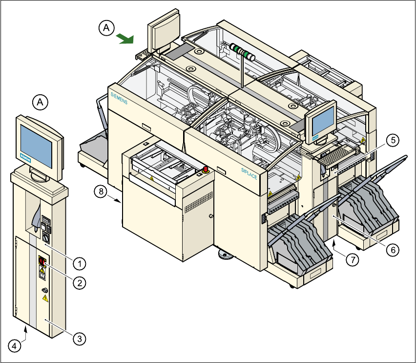
Fig. 3.3 - 1 Electrical and pneumatic connection points on the placement system
3
(1)Operator panel, on the left
(2)Main power switch
(3)Safety door to the power supply unit
(4)Hole for power cable feed-in
(5)Operator panel, on the right
(6)Safety door to the compressed air unit
(7)Hole for compressed air line feed-in
(8)LAN connection on the station computer
3 Technical data User Manual SIPLACE HS-60
3.3 Connection data for the placement system Software version SR.503.xx 07/2003 US Edition
78
WARNING 3
The placement system is supplied with 3 x 204 VAC (US version), 3 x 230 VAC, 3 x 380 VAC,
3 x 400 VAC or 3 x 415 VAC ± 5 %, 50/60 Hz main power voltage. This means that some parts of
the system carry potentially lethal voltages - even when switched off at the main switch. Incorrect
handling of the placement machine can therefore result in death or severe injury or considerable
damage to equipment.
WARNING 3
Never disconnect compressed air lines while they are pressurized. Risk of injury.
3.3.2 Technical data – electrical ratings
Supply voltage 3 x 204 VAC ± 5 %; 50/60 Hz (for the U.S.A. version)
3 x 230 VAC ± 5 %; 50/60 Hz
3 x 380 VAC ± 5 %; 50/60 Hz
3 x 400 VAC ± 5 %; 50/60 Hz (Europe)
3 x 415 VAC ± 5 %; 50/60 Hz
Fuses 3 x 32 A (3 x 204 VAC)
3 x 32 A (3 x 230 VAC)
3 x 16 A (3 x 380 VAC)
3 x 16 A (3 x 400 VAC)
3 x 16 A (3 x 415 VAC)
Total connected load 11.1 kVA
Total power 4 kW
Power failure Max. 20 msec