00193411-02.pdf - 第82页
3 Technical data User Manual SIPLACE HS-60 3.6 Overview of the modules - controls Software version SR.503.xx 07/2003 US E dition 82 3.6 Overv iew of the mo dules - con trols 3.6.1 Controls 3 Fig. 3.6 - 1 Overv iew of the…
User Manual SIPLACE HS-60 3 Technical data
Software version SR.503.xx 07/2003 US Edition 3.5 Dimensions and weight of the placement system
81
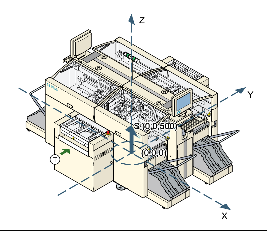
3.5.3 The placement system’s center of gravity
3
Fig. 3.5 - 2 The placement system’s center of gravity
X coordinate 0 mm
Y coordinate 0 mm
Z coordinate 500 mm high
T Direction of PCB transport
These center of gravity coordinates relate to placement systems with a PCB transport height of
830 mm.
3 Technical data User Manual SIPLACE HS-60
3.6 Overview of the modules - controls Software version SR.503.xx 07/2003 US Edition
82
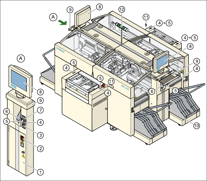
3.6 Overview of the modules - controls
3.6.1 Controls
3
Fig. 3.6 - 1 Overview of the modules - controls
3
(1) Operator panel, on the left (7) Component counter
(2) Main power switch (8) LCD touchscreen
(3) Key-operated switch (9) Keyboard with trackball
(4) Stop button (black) (10) Operator panel, on the right
(5) Start button (white) (11) Emergency stop button
(6) Component barcode reader (option) (12) Indicator lamps

User Manual SIPLACE HS-60 3 Technical data
Software version SR.503.xx 07/2003 US Edition 3.6 Overview of the modules - controls
83
3.6.2 Description
All the controls can be reached by a 1.60 m tall person.
Main switch 3
The main power switch is used to switch the power supply to the placement machine on and off.
RISK OF DEATH
Some parts inside the placement system carry potentially lethal voltages - even when switched
off at the main switch. 3
Key switch 3
In normal mode, the key switch is set to "0". The key should be removed and kept in a safe place.
It must only be turned to position "I" (set-up mode) by authorized personnel, and then only for cer-
tain maintenance and servicing work.
Stop button 3
This button is used to stop the placement machine.
Start button 3
This button starts the placement machine after it has been switched on or after faults have been
eliminated.
Emergency stop button 3
The emergency stop button latches in the ON position when pressed. The power supply to the
gantry axes, the components changeover tables, conveyors, and used tape cutters is interrupted
and the voltage supplied to the star axes of the placement heads is reduced. Turn the button to
release it.
Component counter 3
The component counter displays the number of components processed.
LCD touchscreen 3
There is a flat LCD screen with a touch-sensitive surface (touch-screen) on either side of the
placement system. The screen resolution is 1024 x 768 pixels.