M20_Ope_E - 第100页
Chapter 2 Creating and Editing a Program 2-56 2-7-2-1 Automatic Feeder Link 1 When several pickup data share the same comp onent code, same feeder, and same packaging, they can be linked automatically. The link sequence …

Chapter 2 Creating and Editing a Program
2-55
Shortage Alarm When the remaining component count drops to the level set here, the
shortage alarm signal will be output.
APC The amount of deviation that is measured by vision process is applied
to the Pickup-point correction. Right-click in a [APC] cell to select
either “Enabled” or “Disabled”. The value of 7. Auto Pickup-point
Correction Interval and 8. Auto Pickup-point Correction Tolerance in
User Parameter>Parameters are used.
Optimization Select “Enabled” if the feeder set position (ST No.) can be changed by
optimization. If not, select “Disabled”. (Refer to 3. Optimization.)
Reject / Reuse Specify how the component that has caused an error is to be processed.
Select “Standard (Reject)”, “Specified Location” or “Reject Conveyor”
from the combo box that appears when a right-click is made.
Standard (Reject):
The component will be rejected into the front-side
reject tray if ST-F is selected in [Feed Style], or into the rear-side reject
tray if ST-R is selected. The component will be returned to the tray
from which it was picked up if a feed style other than ST-F and ST-R
(i.e. if any of MX-RT1, MX-ST2, MX-20, MXR(L) and MXR(R) is
selected).
Specified Location
: The component will be rejected into the location
(coordinates) specified in [Reject Location]. The reject location will be
linked with the location specified in the tab page displayed by selecting
System > User Parameter > Reject Location.
Reject Conveyor:
The component will be rejected onto the reject
conveyor attached to the station specified in [Reject Location]. The
reject location will be linked with the location specified in the tab page
displayed by selecting System > User Parameter > Reject Conveyor
Offset.
Note: The return-to-tray of the components picked up from CTF (changeable tray feeder) is performed
after component placement, if “Standard (Reject)” is selected, and after component pickup if
“Specified Location” or “Reject Conveyor” is selected.
Reject Location If “Specified Location” is selected in [Reject / Reuse], set the
component reject location No. (3 to 10) registered to the user
parameters.
If “Reject Conveyor” is selected in [Reject / Reuse], set the component
reject conveyor offset No. (1 to 10) registered to the user parameters.
Chapter 2 Creating and Editing a Program
2-56
2-7-2-1 Automatic Feeder Link
1
When several pickup data share the same component code, same feeder, and same packaging,
they can be linked automatically. The link sequence is automatically optimized for minimizing the
head travel and for enabling simultaneous pickup.
Example:
No. Component Code -- Feed Style ST No.
Feeder Packaging
005 1608CHIP -- ST-F 10 PS-84 Kyokyu1
007 1608CHIP -- ST-F 16 PS-84 Kyokyu1
025 1608CHIP -- ST-R 23 PS-84 Kyokyu1
When pickup data of the PS-MS3 multi-stick feeder are entered as follows, they can be linked. In
use of PS-MS3, different feeder names (PS-MS3-A, -B, ...-I for each attachment position) share the
same station number (where electrical contact between the feeder bank and PS-MS3 is made).
Example:
No. Component Code -- Feed Style ST No.
Feeder Packaging
005 SOP-16 -- ST-F 16 PS-MS3-A Kyokyu2
006 SOP-16 -- ST-F 16 PS-MS3-C Kyokyu2
007 SOP-16 -- ST-F 16 PS-MS3-E Kyokyu2
Accordingly, when pickup data of the MSF-1 multi-stick feeder are entered as follows, they can be
linked. In use of MSF-1, different feeder names (MSF-01, -02, ...-16 for each attachment position)
share the same station number (where electrical contact between the feeder bank and MSF-1 is
made).
Example:
No. Component Code -- Feed Style ST No.
Feeder Packaging
005 SOP-16 -- ST-F 16 MSF-02 Kyokyu2
006 SOP-16 -- ST-F 16 MSF-04 Kyokyu2
007 SOP-16 -- ST-F 16 MSF-06 Kyokyu2
For information about link of trays, see Chapter 5.
1
Link: When a currently used feeder is emptied, link allows the head to move automatically to a spare feeder for
components. This can eliminate machine down time due to changeover.
Chapter 2 Creating and Editing a Program
2-57
2-7-3 Feeder Support Function
The feeder support function enables to reduce pickup errors.
Application
This function is available for paper tapes of component dimensions, 0402, 0603, and 1005. Plastic
embossed tapes are not available.
2-7-3-1 Creating an image data
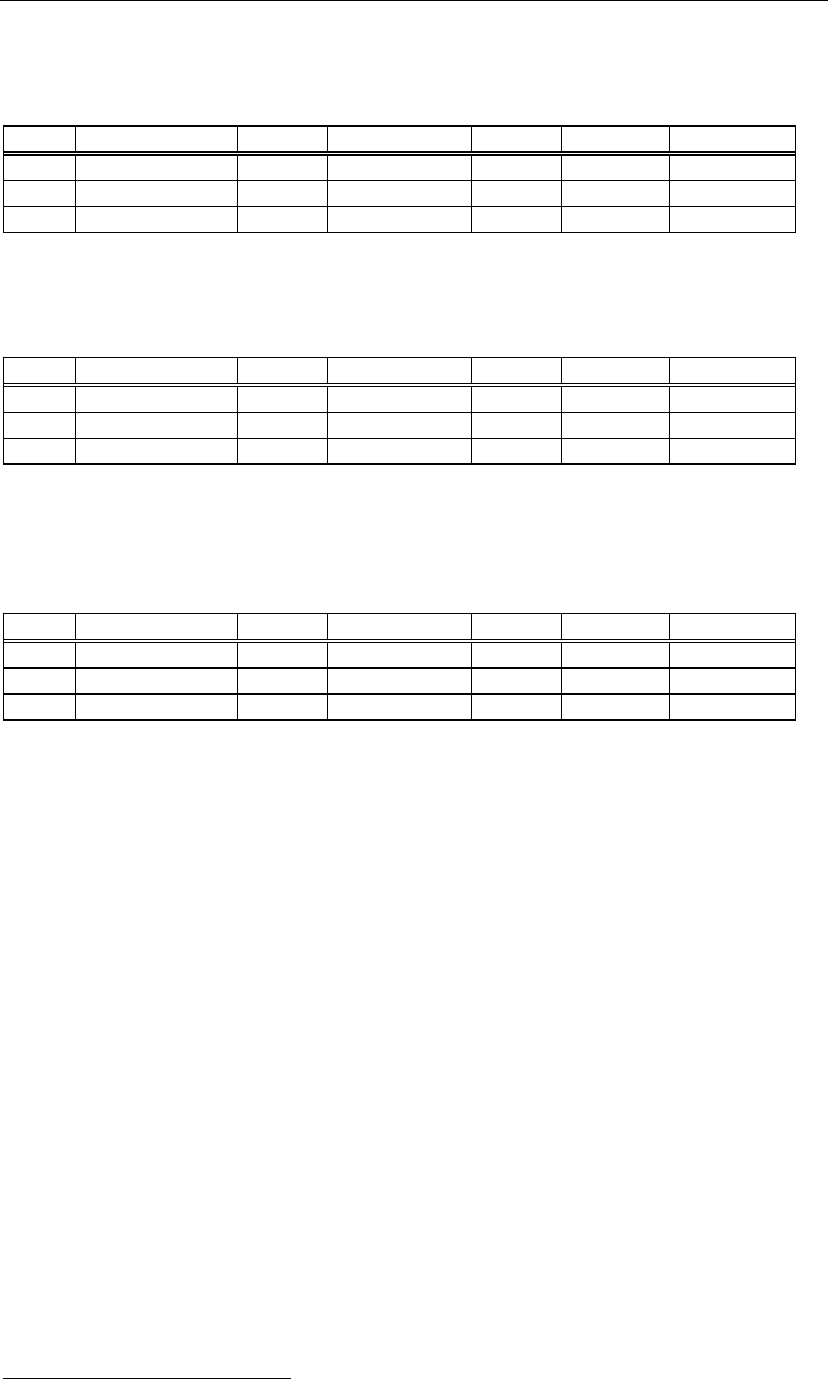
Menu: Program > Pickup Data
Action:
① Move the main teach camera to the pickup point. Double click the blank cell of the [Image
Code for Feeder Support] cell.
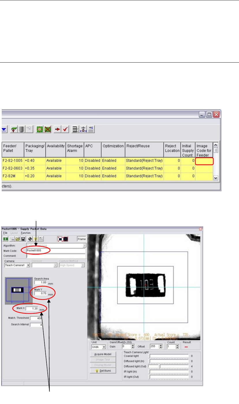
② The image data edit window appears to create a new image data.
Enter the dimensions of
the
p
a
p
er ta
p
e
p
ocket.
Enter an image code.