M20_Ope_E - 第101页
Chapter 2 Creating and Editing a Program 2-57 2-7-3 Feeder Support Function The feeder support function enab les to reduce pickup errors. Application This function is available for paper tapes of component dimensions, …

Chapter 2 Creating and Editing a Program
2-56
2-7-2-1 Automatic Feeder Link
1
When several pickup data share the same component code, same feeder, and same packaging,
they can be linked automatically. The link sequence is automatically optimized for minimizing the
head travel and for enabling simultaneous pickup.
Example:
No. Component Code -- Feed Style ST No.
Feeder Packaging
005 1608CHIP -- ST-F 10 PS-84 Kyokyu1
007 1608CHIP -- ST-F 16 PS-84 Kyokyu1
025 1608CHIP -- ST-R 23 PS-84 Kyokyu1
When pickup data of the PS-MS3 multi-stick feeder are entered as follows, they can be linked. In
use of PS-MS3, different feeder names (PS-MS3-A, -B, ...-I for each attachment position) share the
same station number (where electrical contact between the feeder bank and PS-MS3 is made).
Example:
No. Component Code -- Feed Style ST No.
Feeder Packaging
005 SOP-16 -- ST-F 16 PS-MS3-A Kyokyu2
006 SOP-16 -- ST-F 16 PS-MS3-C Kyokyu2
007 SOP-16 -- ST-F 16 PS-MS3-E Kyokyu2
Accordingly, when pickup data of the MSF-1 multi-stick feeder are entered as follows, they can be
linked. In use of MSF-1, different feeder names (MSF-01, -02, ...-16 for each attachment position)
share the same station number (where electrical contact between the feeder bank and MSF-1 is
made).
Example:
No. Component Code -- Feed Style ST No.
Feeder Packaging
005 SOP-16 -- ST-F 16 MSF-02 Kyokyu2
006 SOP-16 -- ST-F 16 MSF-04 Kyokyu2
007 SOP-16 -- ST-F 16 MSF-06 Kyokyu2
For information about link of trays, see Chapter 5.
1
Link: When a currently used feeder is emptied, link allows the head to move automatically to a spare feeder for
components. This can eliminate machine down time due to changeover.
Chapter 2 Creating and Editing a Program
2-57
2-7-3 Feeder Support Function
The feeder support function enables to reduce pickup errors.
Application
This function is available for paper tapes of component dimensions, 0402, 0603, and 1005. Plastic
embossed tapes are not available.
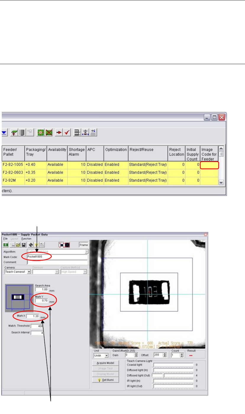
2-7-3-1 Creating an image data
Menu: Program > Pickup Data
Action:
① Move the main teach camera to the pickup point. Double click the blank cell of the [Image
Code for Feeder Support] cell.
② The image data edit window appears to create a new image data.
Enter the dimensions of
the
p
a
p
er ta
p
e
p
ocket.
Enter an image code.
Chapter 2 Creating and Editing a Program
2-58
③
z Instead of creating a new image data, you can copy a pocket type component data from the
master library. (Library > Copy Library > Image)
Select [Pocket 0402], [Pocket 0603], or [Pocket 1005] for the feeder support function.
z The way of creating the image data is same as creating an image data of fiducial mark.
z Enter a mark image code.
z The image process method is the pattern matching. Templates of the pocket models are
prepared. (An appropriate template model is selected automatically for each paper tape.)
z Enter pocket dimensions of the paper tape in the [Mark X] and the [Mark Y].
z Adjust brightness of the pocket displayed in the monitor so that the pocket image becomes
dark and the paper becomes white with the Gain/Offset. Also adjust the Teach camera light.
z You can operate this function whether a component exists in the pocket or not.
z At the end of procedures, be sure to execute image test and the result becomes OK.
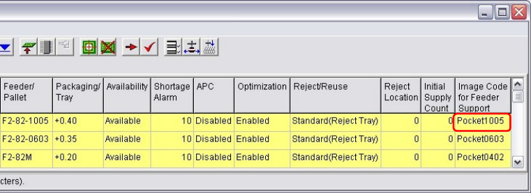
④ Save the image data. Close the window.
⑤ Enter the created image data code in the [Image Code for Feeder Support] cell.
If the cell is empty, the feeder support function does not work.