M20_Ope_E - 第105页
Chapter 2 Creating and Editing a Program 2-61 z When a result of the feeder support function exceeds simultaneous pickup criteria in the component data, simultaneous pickup is not performed. z When result values are with…
Chapter 2 Creating and Editing a Program
2-60
2-7-3-3 Feeder Support Function during a Job Run
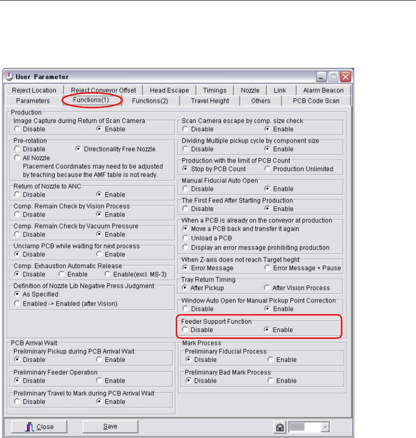
Menu: Parameter > User Parameter > Functions(1)
Action:
① Enable the [Feeder Support Function].
② When this function is enabled, the feeder support function is performed every time at the
start of production for all the pickup points which have image codes in their [Image Code for
Feeder Support] cells and the results are referred to the placements.
The acquired correction values are available until the current job is complete or the stop and
the cancel buttons are pressed.
Note: Not only at the start of production, pickup points are image captured at fixed the interval, after
specific times of pickups are performed, and also when an image capture error or a pickup error
occurs.
Note: Result values acquired by image captures of pickup points are not entered in the [X Offset] and the
[Y Offset], either not saved in the program. Usually the results of this function during production
do not need to be saved. But if you want to save them, click the [Apply] button in Run mode.
Important:
z Paper tapes for component dimensions, 0402, 0603, and 1005 are available.
Plastic embossed tapes are not available.
z The feeder support function works for steps of the feeder styles, ST-F and ST-R. The feeder
styles such as a the CTF tray feeder is not available.
z Make sure the image codes are input in the [Image Code for Feeder Support] cells.
z Make sure paper tapes are used for the specified feeders.
z Make sure the specified pickup points are within movable range of the main teach camera.
The aux. teach camera does not perform this function.
Chapter 2 Creating and Editing a Program
2-61
z When a result of the feeder support function exceeds simultaneous pickup criteria in the
component data, simultaneous pickup is not performed.
z When result values are within simultaneous pickup criteria, the largest correction value and
the smallest correction value are averaged and used it for the simultaneous pickup.
(Largest correction value + Smallest correction value) / 2
(This is the software internal process. X and Y offsets data are not changed.)
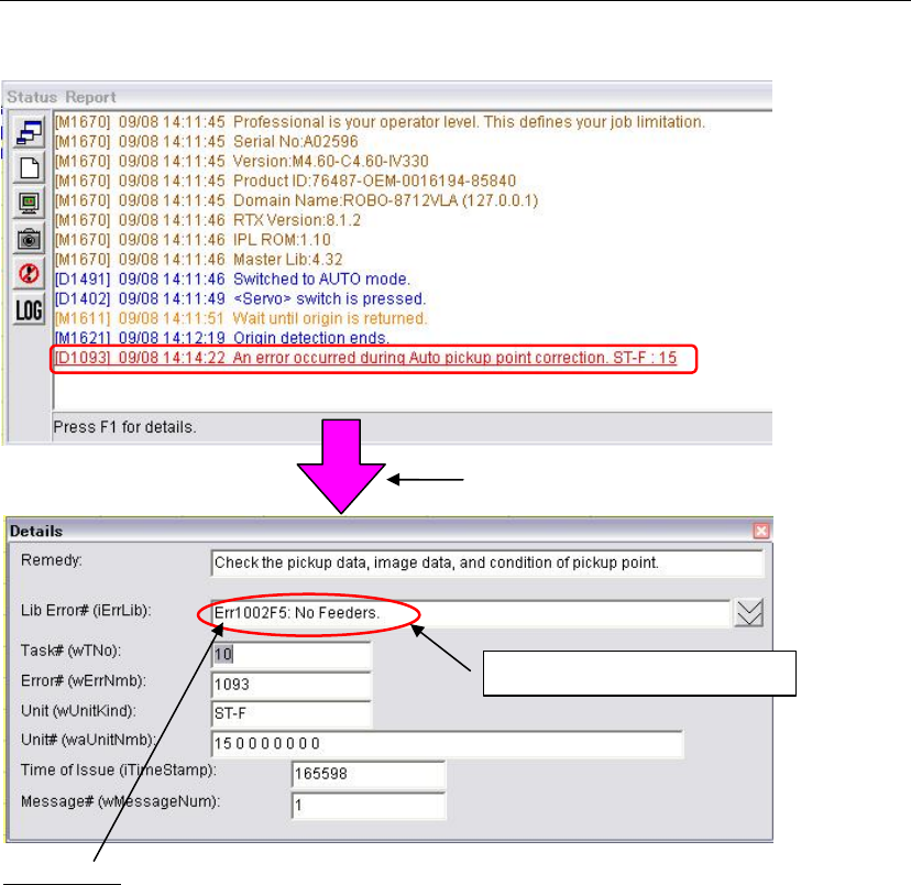
2-7-3-4 Error
If an error occurs, the message appears in red characters.
Press the F1 key to check the error details.
Error details
Err1002F5='No Feeders.'
(A tape feeder is not set at the pickup point.)
Err200233=Auto Pickup Point Correction: Selected feeder incorrect
(Other than ST-F and ST-R is specified in the [Feeder Style].)
Err200235=Auto Pickup Point Correction: No image code specified
(Mark code is not entered in the [Image Code for Pickup Point Correction].)
Err200236=Auto Pickup Point Correction: Feeder lane is out of range
(Selected pickup point is out of movable range of the main teach camera.)
Err200239=Auto Pickup Point Correction: Vision process result error
(Failures such as creating image data, no tape exists at a pickup point, plastic embossed
tape is set.)
Note: For error causes and countermeasures, refer to “Important” described previously.
Press the F1 key to check the error details.
Ex. Err 1002F5 : No feeders.
Chapter 2 Creating and Editing a Program
2-62
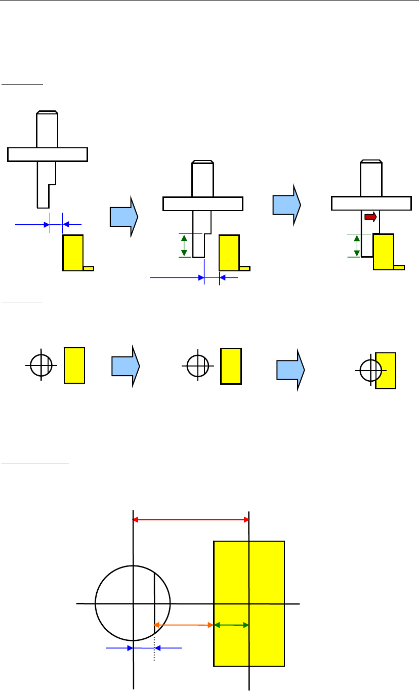
2-7-4 Side Pickup Nozzle
Side Pickup Nozzle picks up a component from its side, therefore the nozzle moves towards X or Y
horizontally.
■ A movement sequence
Side view
Top view
Nozzle at a pickup point Nozzle when the head moves down. Nozzle when the head travels.
Magnified view
Clearance
Clearance
Grip Length
Grip Length
Offset
B
A
C
(A+B+C)