M20_Ope_E - 第116页
Chapter 2 Creating and Editing a Program 2-72 ● Example 2 : When each panel has its own origin 100m m 10m m 100m m 10m m Origin o f each pa nel Distance f ro m panel’s ori gin(X:2 0, Y: 20) Not e: Dista nce from PC B ori…
Chapter 2 Creating and Editing a Program
2-71
2-7-6-3 Block Data Conversion
Menu: Program>DataEditUtilities>BlockDataConversion
If the program contains block data (repeat data), the program data can be converted with each
repeat offset value reflected on each placement coordinate.
However, the method for creating the original repeat data differs between that when all the panels
share the same origin and when each panel has its own origin.
Furthermore, if a mark step is present in the original repeat data, a mark group No. will be
assigned to each block when data conversion is performed.
Note: When the block data is converted and saved, the original block data will be lost. So, it is
recommended that the original block data be saved in another name and then block data
conversion be performed on that data.
Note: Block data conversion cannot be performed if the program is unsaved or contains data check
errors.
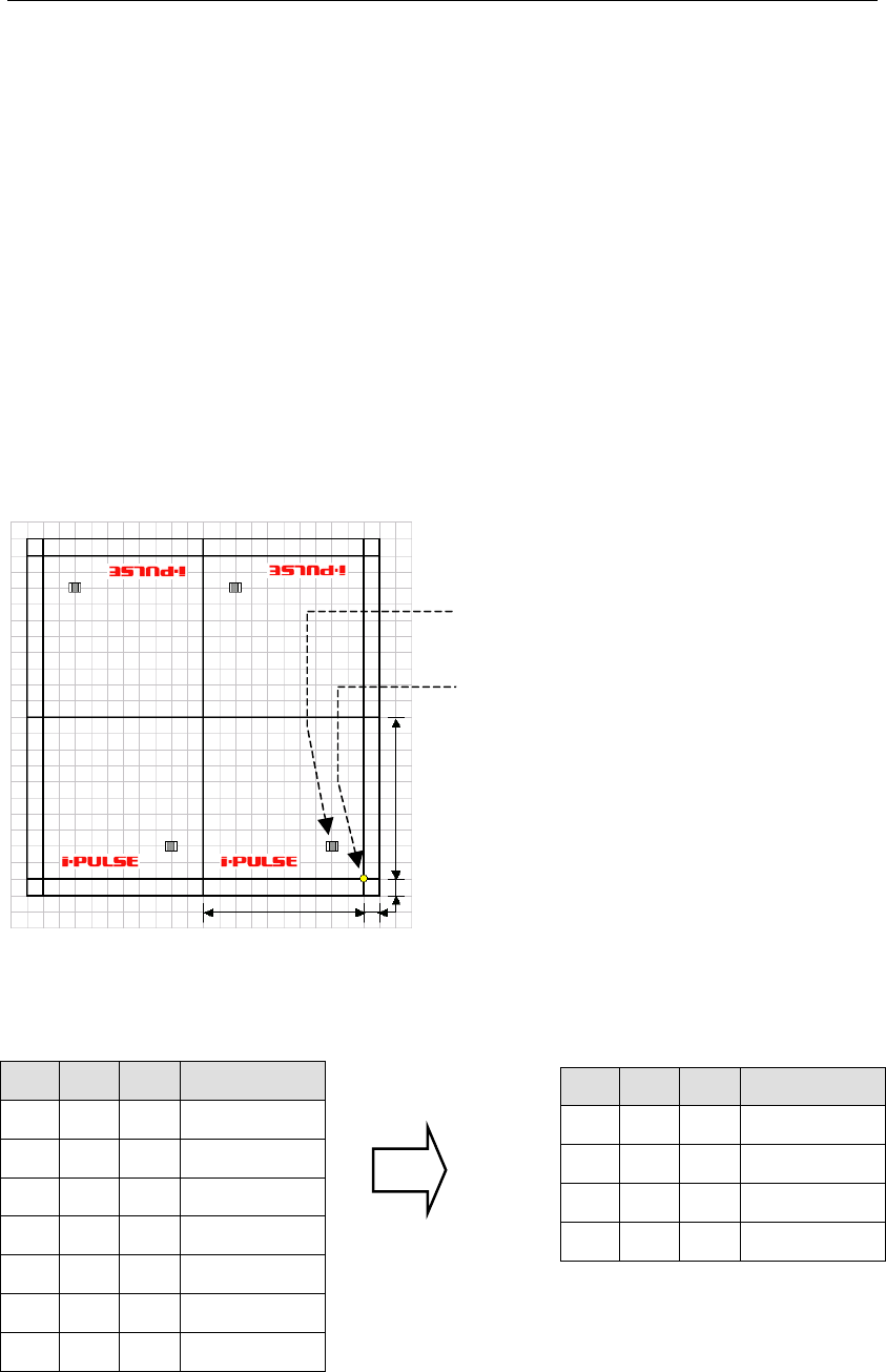
● Example 1 : When all the panels share the same origin (PCB origin X:10, Y:10)
100mm
100mm
10mm
10mm
Origin common to all
the panels
Placement coordinates
(
X:20, Y:20
)
X Y θ Task
Start Block
20 20 0 Single Pickup
End Block
100 0 0 Repeat Offset
100 200 180 Repeat Offset
200 200 180 Repeat Offset
X Y θ Task
20
20 0 Single Pickup
120
20 0 Single Pickup
80 180 180 Single Pickup
180
180 180 Single Pickup
Repeat data before conversion
Actual coordinates after conversion
Chapter 2 Creating and Editing a Program
2-72
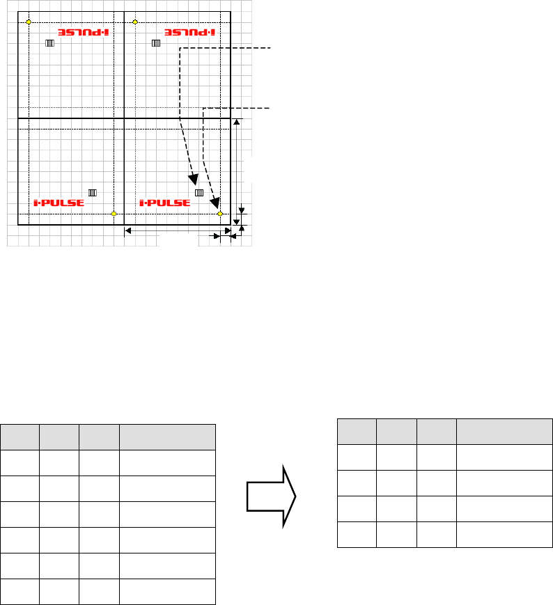
● Example 2 : When each panel has its own origin
100mm
10mm
100mm
10mm
Origin of each panel
Distance from panel’s origin(X:20,Y:20)
Note: Distance from PCB origin(X:30,Y:30)
Since only one PCB origin is specified, it is not possible to duplicate (repeat) data by rotating the
PCB whose origin has been offset. When each panel has own its origin as shown above, set the PCB
origin to X:0 and Y:0. As a result, the first component placement coordinates will be X:30, Y:30 in
the case of the above example.
PCB origin (X:0,Y:0)
X Y θ Task
Start Block
30 30 0 Single Pickup
End Block
100 0 0 Repeat Offset
100 200 180 Repeat Offset
200 200 180 Repeat Offset
X Y θ Task
30
30 0 Single Pickup
130
30 0 Single Pickup
70 170 180 Single Pickup
170
170 180 Single Pickup
Repeat data before conversion
Actual coordinates after conversion
Chapter 2 Creating and Editing a Program
2-73
2-7-6-4 Creating Multi-panel
Menu: Program>DataEditUtilities>CreatingMulti-panel
This function enables easy generation of repeat data based on placement data that contains no
repeat data. Repeat data (panel) can be angled by 0 or 180 degrees from the original placement
data.
Note: There is no restriction on the number of panels. However, an error will occur if the completed
placement data consists of more than 10,000 lines. Furthermore, this function cannot be used if the
original data contains repeat data or if a data check error is present.
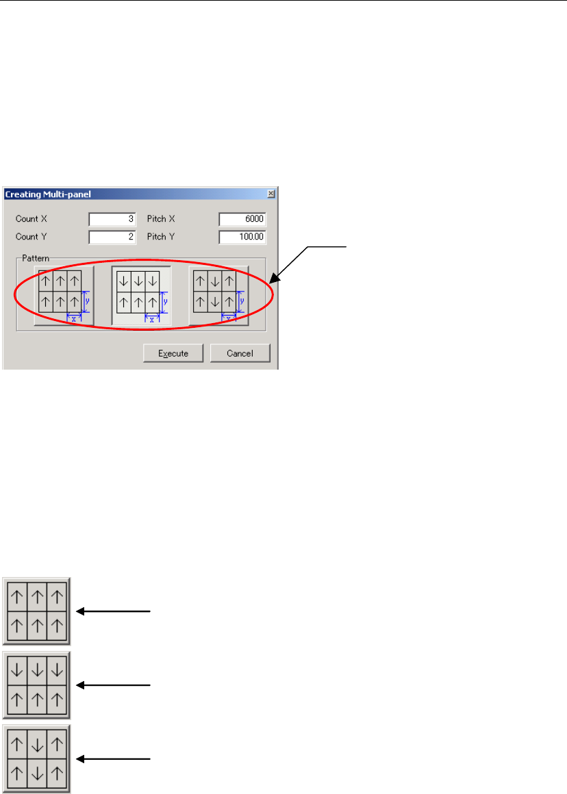
Panel layout pattern
selection button
Item:
Count X / Y Enter the number of panels present in X (horizontal) and Y (vertical)
directions. The original panel must be contained in this number.
Pitch X / Y Enter the panel pitch in X (horizontal) and Y (vertical) directions. The
panel’s edge length must always be entered here even if a number
other than “1” is entered in Count X/Y.)
★Unit: mm
Pattern Select the desired panel layout pattern.
A
ll the panels are placed in the same direction (i.e. at 0 degree from) as the original
placement data.
When panels lined up in X-direction are placed in the same direction (i.e. at 0 degree
from) as the original placement data, and panels lined up in Y-direction are placed in
reverse direction (i.e. at 180 degrees)
Note: Panels in Y direction are angled at 0 and 180 degrees alternately: third-row at 0
degree and fourth-row at 180 degrees.
When panels lined up in Y-direction are placed in the same direction (i.e. at 0 degree
from) as the original placement data, and panels lined up in X-direction are placed in
reverse direction (i.e. at 180 degrees)
Note: Panels in X direction are angled at 0 and 180 degrees alternately: third-row at 0
degree and fourth-row at 180 degrees.
Note: No other patterns are supported by the multi-panel PCB generation function.
To have a pattern other than those, repeat data must be created manually. For details, refer to
“Rotated Multi-Panel PCB”.