M20_Ope_E - 第123页
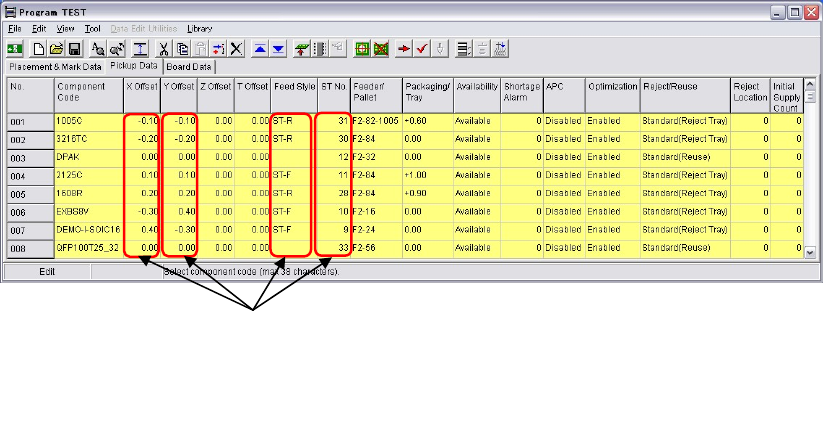
Chapter 2 Creating and Editing a Program 2-79 ④ The converted data will be em bedded in the pickup data. ⑤ Execute optimization. Data of these four column will be converted. 1. X Offset 2. Y Offset 3. Feed Style 4. ST No…
Chapter 2 Creating and Editing a Program
2-78
2-7-6-7 CFB Front/Rear Relocation
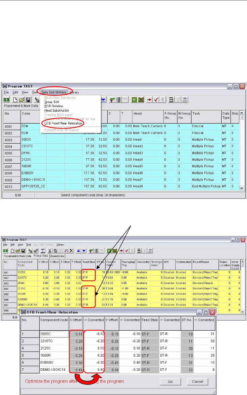
Menu: Program>Data Edit Utilities>CFB Front/Rear Relocation
When the CFB (Changeable Feeder Bank) is relocated from the front to the rear of the mounter and
vice versa, the pickup data can be converted for the relocated CFB by executing the [CFB
Front/Rear Relocation] menu.
Note: Once the CFB Front/Rear Relocation is executed, the original pickup data won’t be recovered.
It is recommended to execute pickup data conversion on a renamed program to secure the original
program.
Action:
① Click the [CFB Front/Rear Relocation] menu.
② The window is switched to [Pickup Data] and the [CFB Front/Rear Relocation] window
appears at the same time. In the [CFB Front/Rear Relocation] window, data to be converted
appear as follows.
In the [CFB Front/Rear Relocation] window, each original and converted data are shown in
columns side by side. The original data is in a left column and the converted data is in its right
column.
③ Check the result of the converted data. Click the <OK> button.
Data of Feeder styles, ST-F and ST-R will be
converted by the [CFB Front/Rear Relocation].
Chapter 2 Creating and Editing a Program
2-79
④ The converted data will be embedded in the pickup data.
⑤ Execute optimization.
Data of these four column will be converted.
1. X Offset
2. Y Offset
3. Feed Style
4. ST No.

Chapter 2 Creating and Editing a Program
2-80
2-8 Checking a Program
Several functions for checking a created program/library data are available.
2-8-1 Checking a Program
Menu: Program>File>CheckProgram
This feature allows for checking a created program (placement program and associated library
data) for error settings. The feature is automatically performed when you save a program in the
program editor or open a program in the Run dialog box. When errors are detected, error
messages are provided in [Check Program] dialog box.
When you correct library data according to the provided error message, save the library data and
check the data in one of the following three ways:
Open the corresponding program and execute [Check Program] menu
(Program>File>CheckProgram).
Open the corresponding program and save the program (Program>File>Save).
When [Check Program] dialog box is open, execute the Recheck menu (File>Recheck).
The error message “Nozzle No. registered in Component Library is not found in Nozzle
information.” which may be provided in checking a program does not suggest an error setting.
When this error message is provided, execute [Scan ANC] operation in the Nozzle dialog box
(Manual>Nozzle) to let the system identify present nozzles.
Note: This feature is applicable only to saved data.
2-8-2 Program Trace
Menu: Program>Tool>Teach>Trace
This feature allows programmed coordinates (placement/pickup/fiducial) to be monitored on the
CRT monitor. See Teach Entry earlier in this chapter.
2-8-3 Programmed Components & Nozzles
Menu: Program>Tool>ProgrammedComponents&Nozzles
When you edit a program in the program editor, you can refer to component and nozzle
information used in the program.
[Component] ················· shows the used component list, which is quoted from the component library.
[Programmed Nozzle] ····· shows the maximum number of nozzles used by the program
[Nozzle Arrangement] ···· shows the nozzle arrangement in the ANC.
(You do not have to replace nozzles. Nozzles will be automatically
arranged when production starts.)
[Fixed Nozzle] ··············· shows nozzles where to assign when ANC (option) is not installed.