M20_Ope_E - 第128页
Chapter 2 Creating and Editing a Program 2-84 2-8-4 Tact Simulation Menu: Tool>TactSimulation Tact simulation calculates approximate time required to run a program. Overview Select a program Click the Start button V…
Chapter 2 Creating and Editing a Program
2-83
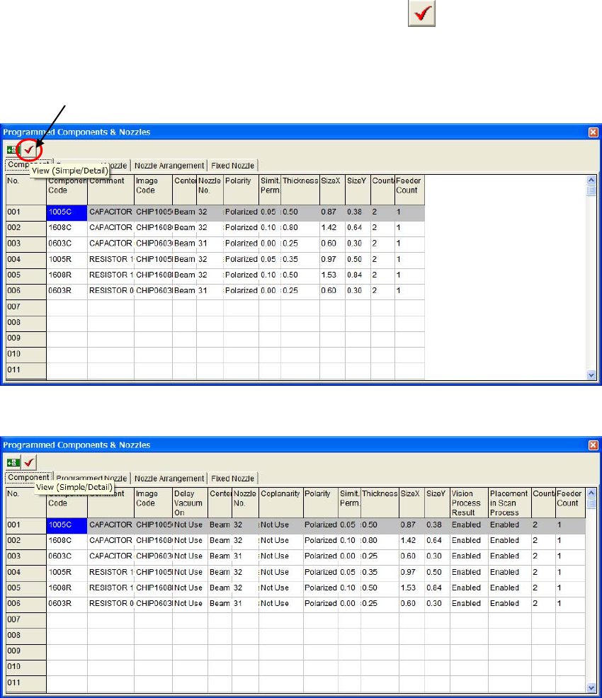
Switching Simple/Detail View
You can switch window views by clicking the View (Simple/Detail)
button in the
[Programmed Components & Nozzles] window. Always the simple view appears the first.
z Simple view
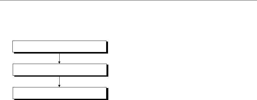
z Detail view
In the detail view, the following four more columns appear.
z Delay Vaccum OK
z Coplanarity
z Vision Process Result
View (Simple/Detail)
Chapter 2 Creating and Editing a Program
2-84
2-8-4 Tact Simulation
Menu: Tool>TactSimulation
Tact simulation calculates approximate time required to run a program.
Overview
Select a program
Click the Start button
View the result
Action:
Selecting a Program
① In the Tact Simulation dialog box, click File>Open. The Select Program dialog box appears.
② Select a file with a click.
③ Click <OK> button.
Executing Tact Simulation
Click <Start> button to execute tact simulation. Progress of the execution is indicated at the lower
part of the dialog box.
To abort execution, click <Cancel> button.
Displaying the Result
The calculated tact time is shown at the middle of the Tact Simulation dialog box. (unit: ms) For
detailed results, click <Result> button. The following information will be displayed.
z Head tab
With respect to each head, counts of pickups, placements, image processes, and nozzle changes are
displayed.
z Time tab
Each operating time stated below is shown:
Pickup Time, Place Time, XY Move Time, Theta Wait Time, Image Shoot Time, Image Process
Time, Component Supply Time, Nozzle Change Time, FM/BM Time (Fiducial/Bad mark time),
and Total Time
z Warning tab
If a
warning message is provided, open this tab for detailed contents.

Chapter 2 Creating and Editing a Program
2-85
2-8-4-1 Customizing Tact Simulation
To obtain even accurate results or suit your specific programming, you can customize tact
simulation with various options. In the Tact Simulation dialog box, select Option>Set to open the
Set dialog box.
Nozzle tab
Tact simulation collects nozzle information from the program, allocating nozzles to the ANC and
heads so the number of nozzles are minimized. This may, however, result in increased nozzle
changes. If necessary, add some nozzles in the following steps.
When you want to customize nozzle allocation, check [Keep this setting.] check box, and perform
as follows:
Action:
① Click a cell in the Nozzle column to enter nozzle name.
② Right-click the mouse and select [Nozzle Select] from the popup menu. The list of nozzles
appears.
③ Double-click a desired nozzle name from the list.
④ The selected nozzle name is entered into the cell.
To delete a nozzle name, right-click the mouse with the nozzle name selected and select [Delete]
from the popup menu.
Note: Nozzle setup will change the tact time. However, changes made here won’t be applied to the
parameter setting of the system.
Feeder Type tab
Feeder types information is collected from the feeder library. You can edit [Feeder Type] and [Feed
Time] as follows:
① Click the record to edit.
② Right-click the mouse and select “Edit” from the provided list.
③ The editor window will appear. Edit [Feeder Type] using the provided combo box, [Feed
Time] by typing.
For information on the feeder drive method, see the Parts Feeders Instruction Manual. For standard
value for the record, click [Initialize] in the list. For standard value for all the records, click
[Initialize All] in the list.
Actuator tab
In the Actuator tab, settings stated below can be changed: [PCB Clamp Time], [PCB Transfer Time],
and [ANC Slide Time].
Note: For the Actuator tab settings, you can use measurements obtained via Manual>Actuator>Timing.
Simulation Cycle tab
Choose [Completion of PCB Clamp to Completion of Placement] or [Including PCB Clamp Time
and PCB Transfer Time] button. The feeder standard feed time here is applied to [Initialization] of
[Feeder Type].
Image Process Time tab
Codes in this tab are related to the image library. This tab provides the following functions:
z Image process time for each code can be changed. (unit: ms)
z New codes can be added. Right-click the mouse and select [New] from the popup menu. The
New Image Code dialog box appears. Type in a code to the entry field. Or click <Image
Library> button to select a code from the image library. After entering a code, click <OK>
button. The dialog box is closed, and the code will be added.
z Codes can be deleted. Right-click the mouse with a code selected. Select [Delete] from the
popup menu. [Data will be deleted. OK?] appears. Click <OK> button.