M20_Ope_E - 第142页
Chapter 4 Data Conversio n 4-4 4-1-3-1 Selecting a CAD Format Select Tool>CAD Data and the CAD Data Conv ersion dialog box appears. Some standard format files are pre-registered. See Appendix later in this chapter. Cl…
Chapter 4 Data Conversion
4-3
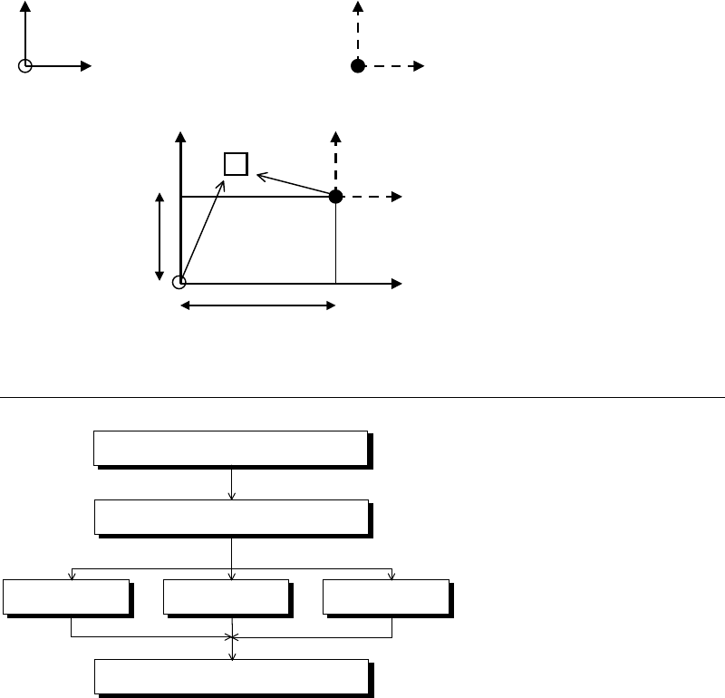
If CAD-data origin is on different coordinates from destination-data origin, placement
coordinates are automatically corrected by entering the distance between these two origins.
CAD data coordinates Destination data coordinates
YY
Component
X
Y Offset
X
X Offset
4-1-3 Operation Overview
Select a CAD format
Create a new fileEdit an existing fileUse an existing file
Execute conversion
Specify a CAD data file
Chapter 4 Data Conversion
4-4
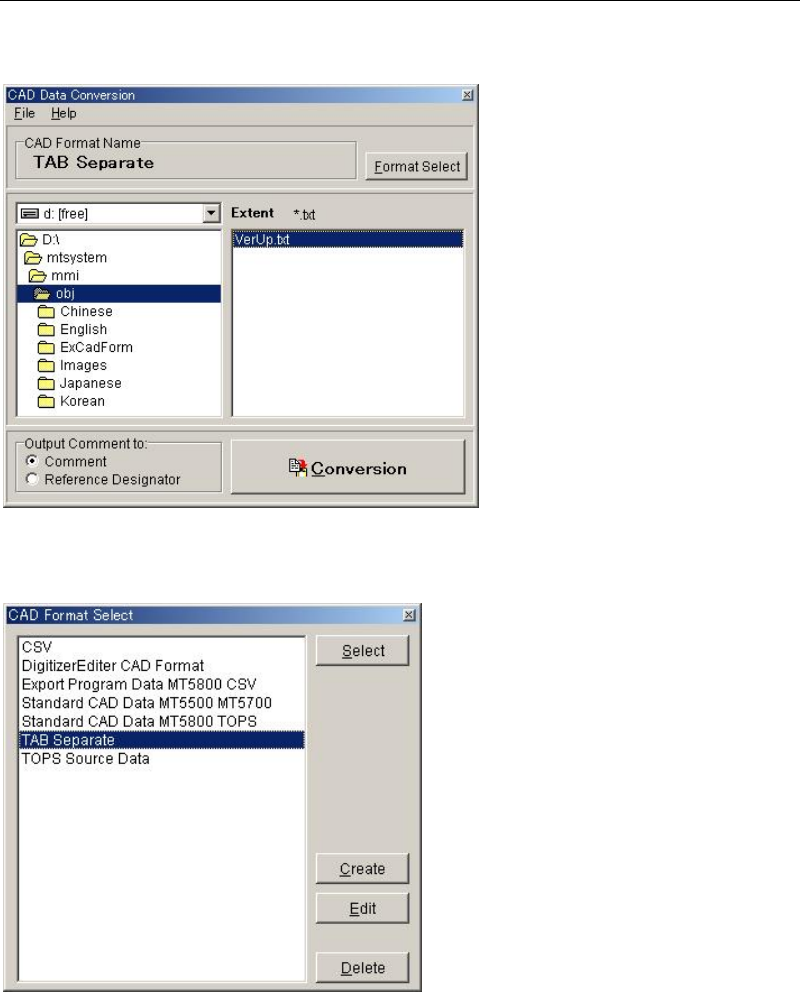
4-1-3-1 Selecting a CAD Format
Select Tool>CAD Data and the CAD Data Conversion dialog box appears. Some standard
format files are pre-registered. See Appendix later in this chapter.
Click <Format Select> button in the above dialog box. [CAD Format Select] dialog box will
appear.
Select what to do from the four alternatives stated below:
Using an existing format
Click a format name and then <Select> button. For the remaining steps, see Selecting a CAD
Data later in this chapter.
Editing an existing format
Click an existing format name and [Edit] button.
Creating a new format
Click <Create> button.
Deleting a format
Click the format to be deleted and <Delete> button.
Chapter 4 Data Conversion
4-5
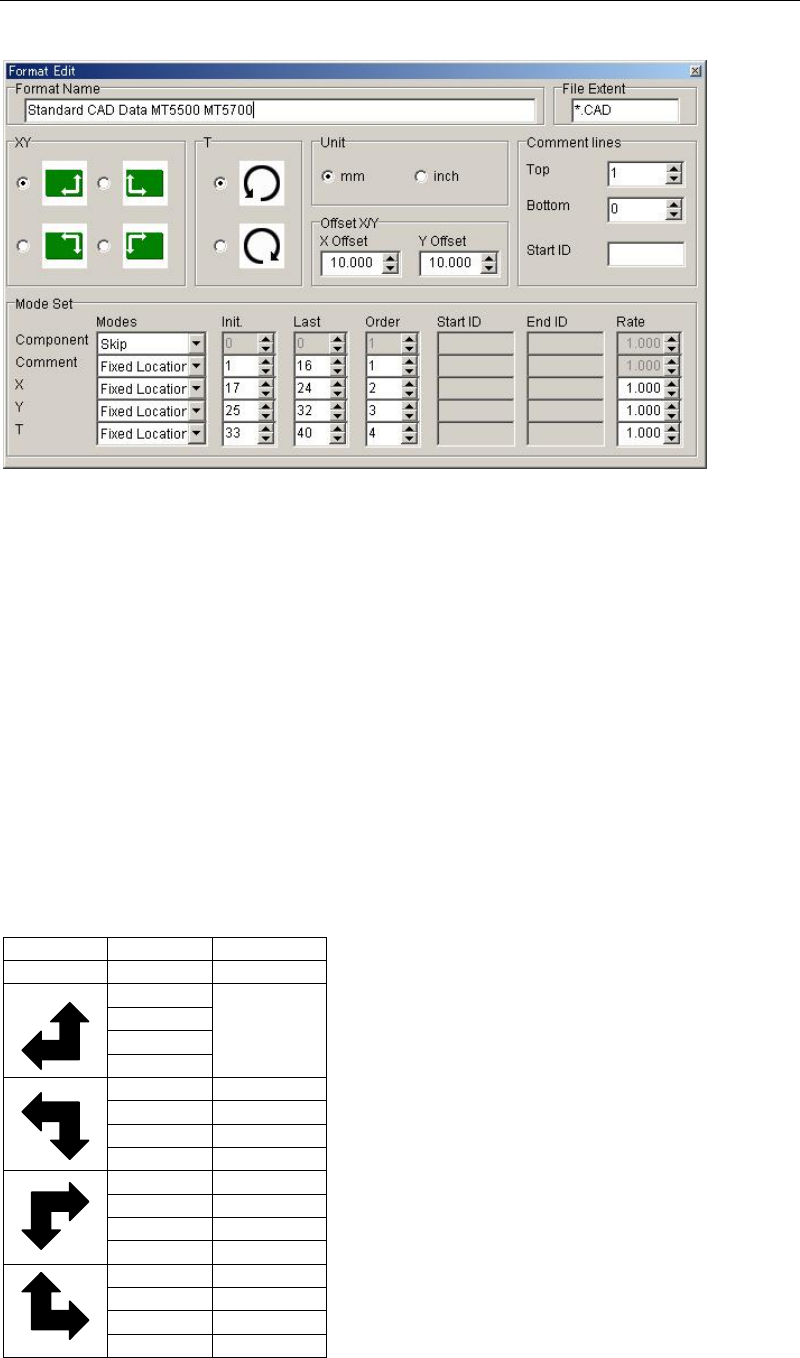
4-1-3-2 Editing and Creating a CAD Format
When clicking <Create> button or <Edit> button, [Format Edit] dialog box will appear.
Format Name
Enter CAD format name. Up to 40 characters can be entered. The name entered here is
displayed for [CAD Format Select] dialog box.
File Extent
Enter file extent of a CAD Data file to which the currently edited format is applied. Prefix *.
(asterisk and period) before the extent. Capital letter and small letter are not separately
recognized.
Example: *.pnc *.CCP
For [CAD Data Conversion] dialog box, only the files assigned the file extent entered here are
displayed.
XY
Using the SPACE key, select the X,Y-axis direction of CAD data. (+ direction is indicated by an
arrow.) If the X,Y-axis direction of CAD data and destination data differ, +/- sign of CAD data
is converted according to the X,Y-axis direction of destination data.
Format CAD Data PCB Origin
XY X/Y RF
+/+ Same as
CAD Data
+/-
-/-
-/+
+/+ +/-
+/- +/+
-/- -/+
-/+ -/-
+/+ -/-
+/- -/+
-/- +/+
-/+ +/-
+/+ -/+
+/- -/-
-/- +/-
-/+ +/+
T
Select the rotating direction (clockwise/couterclockwise) for T angle. (+ direction is indicated
by an arrow.) Since the rotating direction of destination data is fixed as couterclockwise
direction, if you select clockwise direction here, +/- sign of CAD data is reversed.