M20_Ope_E - 第146页
Chapter 4 Data Conversio n 4-8 ● End ID End-identifier letters (up to 10 letters) Us ed for END-ID.m ode and START/END-ID.mode. Space(s) only (with no other letter) are not allowed. As for the last item in a line, if no …
Chapter 4 Data Conversion
4-7
CAD DATA (
↓
=CR&LF (0d0a)h)
●
●
●
●
+
●
●
●
●
1
●
●
●
●
+
●
●
●
●
2
●
●
●
●
+
●
●
●
●
3
●
●
●
●
+
●
●
●
●
4
●
●
●
●
+
●
●
●
●
5
●
TOP B
O
A
R
D
N
A
M
E:
A
B
C
D
EF
G
↓
B
O
A
R
D
O
FFSET : X =
0
.0
m
m,
Y
=0.0
m
m
↓
*****************
P
A
R
TS
M
O
U
N
TED **************
*
N
A
M
EP
A
R
TT
Y
PE X Y T
↓
START ID **** LSI ***
↓
LS101 1SS187 -13. 843 16. 929 0. 00
↓
LS102 1SS187 -
1
5. 519 16. 955 180. 00
↓
↓
****
C
H
IP **
*
↓
R
1
C
R
1/ 4W - 28. 689 7. 544 0. 00
↓
R
2
R
3216 - 42. 596 45. 872 90. 00
↓
R
3
R
32
16 - 44. 094 29. 134 180. 00
↓
↓
BOTTOM
D
A
TE : 1994. 12. 13
↓
TI
M
E: 1
0
: 32: 1
2
↓
[E
O
F]
Mode Set
Specify data search method for non-standard-format CAD data.
● Modes
Data search mode (1-04)
Skip mode: Data is not used.
Fixed location: Detect data by INIT.,LAST and ORDER. Set the initial and last column number
or each data in a line.
END-ID. mode: Detect data by ORDER and END-ID.
By detecting END-ID., the system recognizes the end of data.
Note: It is invalid to locate data of END-ID. after data of START-ID.mode. The system cannot
distinguish one data from the other.
START-ID. mode: Detect data by ORDER and START-ID.
By detecting START-ID.,the system recognizes the starting of data.
START/END-ID. : Detect data by ORDER, START-ID.and END-ID.mode By detecting
START-ID. ,the system recognizes the starting of data. Then by detecting END-ID., the system
recognizes the end of data.
● Init.
Initial column number in a line (1-510)
Used for fixed location mode. Entry value should be the same or less than that of LAST (last
column.number) of the same data. Also each data location in a line assigned by INIT./LAST
should not overlap each other.
● Last
Last column number in a line (1-510)
Used for fixed location mode. Entry value should be the same or larger than that of
INIT.(Initial column.number) of the same data. Also each data location in a line assigned by
INIT./LAST should not overlap each other.
● Order
Data location order (1-99)
ORDER is required for all the data search mode except for 0=Skip mode. ORDER should be
entered in consecutive order from 1. If you want to skip one or more items in a line, you need
not conform to this convention. (See Note.)
● Start ID
Start-identifier letters (up to 10 letters) Used for START-ID.mode and SART/END-ID.mode.
Space(s) only (with no other letter) are not allowed.
Chapter 4 Data Conversion
4-8
● End ID
End-identifier letters (up to 10 letters) Used for END-ID.mode and START/END-ID.mode.
Space(s) only (with no other letter) are not allowed. As for the last item in a line, if no END-ID.
is entered, CR&LF code (0D0A) is recognized as END-ID. instead. However, this code cannot
be entered as END-ID, enter any letters as dummy END-ID.
Note: To skip one or more items in a line, two alternatives are available.
1.Specify Fixed location mode for all the items.
2.Provided the same END-ID. are entered for every item in a line, specify END-ID. mode for
all the items and enter the same END-ID. for them.
In both cases, the system recognizes items to skip by skipped ORDERs.
The following shows example CAD data and the required settings for them (CAD FORMAT
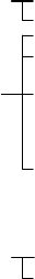
SET). The example CAD data conform to the below conventions:
↓ CR&LF code (0A0D)h
? Data to skip (unnecessary data)
Data search range
START-ID. or END-ID.
(x) ORDER
Example1: [CAD Format Set]
Component
:
Mode=Fixed Location Order=1 Init.= 1 Last=16
X
:
Mode=Fixed Location Order=2 Init.=17 Last=24
Y
:
Mode=Fixed Location Order=3 Init.=25 Last=32
Component X Y
●●●●
+
●●●●
1
0
●●●●
+
●●●●
2
0
●●●●
+
●●●●
3
0
●●●●
+
●●●●
4
0
●
02CZ +43.244 40.868
↓
1SS322 62.294 23.851
↓
1SS322 -162.294 128.296
↓
(01) (02) (03)
Example2: [CAD Format Set]
Component
:
Mode=Start/End ID Order=1 Start ID=NT: End ID=/
X
:
Mode=End ID Order=2 End ID=/
Y
:
Mode=Start ID Order=3 Start ID=/
●●●●
+
●●●●
1
0
●●●●
+
●●●●
2
0
●●●●
+
●●●●
3
0
●●●●
+
●●●●
4
0
●
POINT: 02CZ/ +43.224/ ??/ 40.868
↓
POINT:1SS322/62.294/????/
23.
851
↓
POINT: 1SS322/ -
1
62.294/ ??/ 128.296
↓
(01) (02) (03)
Example3: [CAD Format Set]
Component
:
Mode=End ID Order=2 End ID=/
X
:
Mode=End ID Order=5 End ID=/
Y
:
Mode=End ID Order=6 End ID=/
●●●●
+
●●●●
1
0
●●●●
+
●●●●
2
0
●●●●
+
●●●●
3
0
●●●●
+
●●●●
4
0
●
??/02CZ/???/??/+43.244/40.866
↓
???/1SS322/??/???/62.294
/
23.
851
↓
??/1SS322/???/????/ -
1
62.294/128.296
↓
(01) (02) (03) (04) (05) (06)
Example4: [CAD Format Set]
Component
:
Mode=Start/End ID Order=3 Start ID=[ End ID=]
X
:
Mode=Start ID Order=1 Start ID=X
Y
:
Mode=Start/End ID Order=2 Start ID=Y End ID=K
●●●●
+
●●●●
1
0
●●●●
+
●●●●
2
0
●●●●
+
●●●●
3
0
●●●●
+
●●●●
4
0
●
X+43.244Y+40.868K?????????[02CZ]
↓
X+62.294Y
+23.
851K??????[1SS322]
↓
X-
1
62.294Y+128.296
K
??????[1SS322]
↓
(01) (02) (03)
Chapter 4 Data Conversion
4-9
● Rate (Data correction rate)
CAD data and destination data (program data/pre-optimization data) may have different
data-entry unit. For this case, enter data correction rate by which to multiply CAD data into
destination data in correct unit.
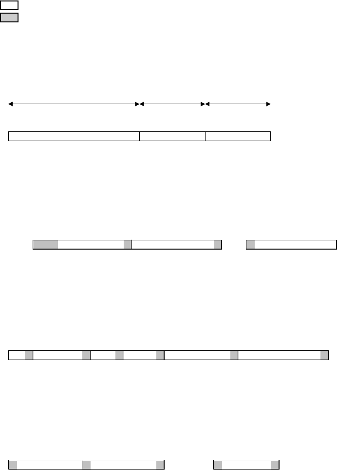
Example: If convert CAD data=123.456inch with the below listed correction rates, the destination data
will be as follows.
CAD Data CAD Format Destination Data
Unit Rate Unit
inch mil 1/10 mil mm
10.000 1234.56 1234560 12345600 31357.824
01.000 123.456 123456 1234560 3135.7824
00.100 12.3456 12345.6 123456 313.57824
123.456 inch 00.010 1.23456 1234.56 12345.6 31.357824
00.001 0.123456 123.456 1234.56 3.1357824
02.000 246.912 246912 2469120 6271.5648
00.500 61.728 61728 617280 1567.8912
Note: It is invalid set such RATE as to make the number of integer places of destination data exceeds
the limit. As for the decimal part, exceeded places are rounded off.
After entering data for the Format Edit dialog box...
① Close the Format Edit dialog box by clicking its <X> button. The confirmation dialog
appears asking you whether to save the setting. Click <Yes> button.
② The CAD Format Select dialog box becomes active. Click the CAD format name saved in
the previous step and click <Select> button.
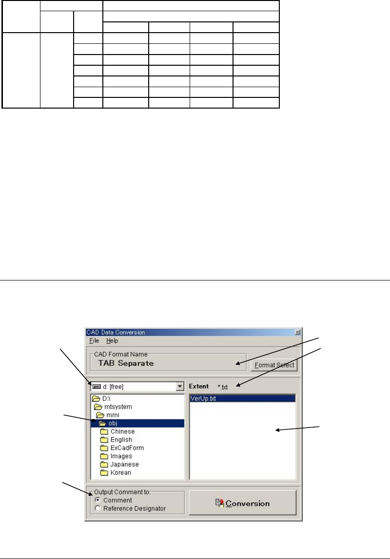
③ The CAD Data Conversion dialog box becomes active. Make sure the CAD format name
selected in the previous step is shown under [CAD Format Name].
4-1-3-3 Selecting a CAD Data
Select a CAD data.
4-1-3-4 Executing Convertion
Click <Execution> button to execute conversion. After the execution, save the data.
Note: You can change a file name. However, saving the renamed file to a different folder is not
allowed.
The saved data can be loaded to the program editor (Program>File>Open).
Select the drive
including CAD data
you want to use.
Select the folder
including CAD data
you want to use.
Select the file
Including CAD data
you want to use. Only
the files with the
specified extent will
appear.
The selected format and
extent should be
displayed.
Select to which data of
the program data
Comment is output.