M20_Ope_E - 第149页
Chapter 4 Data Conversio n 4-11 4-1-4-2 Standard CAD Data Layouts The following standard formats are pre-registered. Standard CAD Data for MT-5500 MT-5 700 File Style: Text file File Name: *.* Long file name is supp or…

Chapter 4 Data Conversion
4-10
4-1-4 Appendix
4-1-4-1 Applicable CAD Data
Applicable CAD data for the enhanced CAD data conversion should meet the following
requirements.
● CAD data should conform to ASCII codes. (text file)
Numerals: "0"(30)h ~ "9"(39)h "+"(2B)h, "-"(2D)h, "."(2E)h
Other characters: "(space)"(20)h/(09)h*, "~"(7E)h, etc. * TAB code (09)h represents a
space.
● File specifications
Ending of file: EOF code (1A)h
Ending of line: CR&LF code (0A0D)h
Line length: Max.512 bytes (Including CR&LF code)
Numerical data: Expressed in decimal
COMMENT LINES: CR&LF code or any identifier letters are entered at the beginning.
● Placement information for one side of board and that for the other side should not be
included in the same file. If so, you need to separate each information into different files,
or to modify the converted data.
● Placement and dispense information should not be included in the same file. If so, you
need to separate each information into different files, or to modify the converted data.
● As for placement step, X,Y-data should represent coordinates of placement point.
Normally, the Tenryu placement head sucks the parts-center and its coordinates
correspond to placement point. (Coordinates of parts-corner or parts-lead are invalid.)
As for dispense step, X,Y-data should represent coordinates of dispense point.
Chapter 4 Data Conversion
4-11
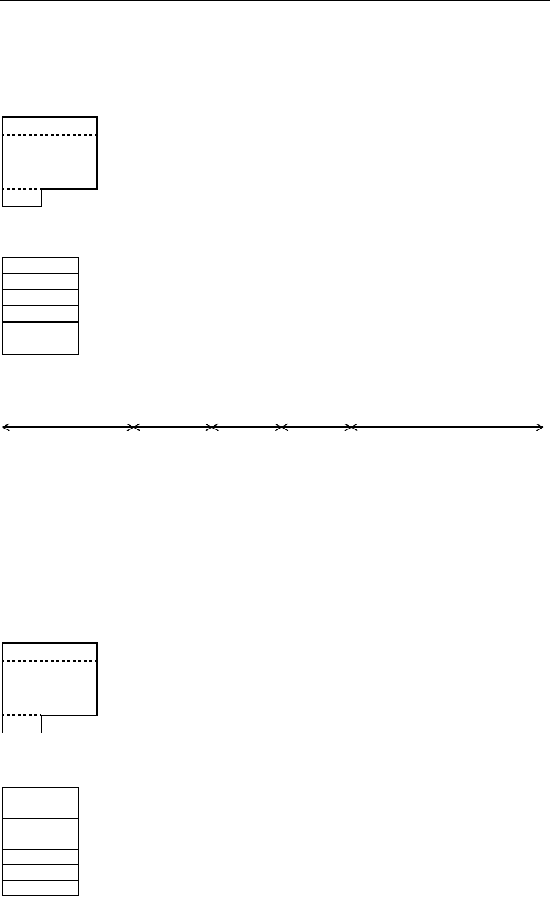
4-1-4-2 Standard CAD Data Layouts
The following standard formats are pre-registered.
Standard CAD Data for MT-5500 MT-5700
File Style: Text file
File Name: *.* Long file name is supported.
File Layout:
Data record 64 bytes per step x n
.
n is determined by number of steps
.
of destination data.
.
EOF (1A)h
Data Record Layout:
Comment 16 bytes 16 or less letters
X 8 bytes +/- XXX.XXX[mm]/[inch]
Y 8 bytes +/- XXX.XXX[mm]/[inch]
T 8 bytes +/- XXX.XXX[mm]/[inch]
Reserve 22 bytes (space)x22
Control code
2 bytes
(0DOA)h
Sample CAD Data:
Comment
X
Y
T Reserve
●
●
●
●
+
●
●
●
●
1
●
●
●
●
+
●
●
●
●
2
●
●
●
●
+
●
●
●
●
3
●
●
●
●
+
●
●
●
●
4
●
●
●
●
+
●
●
●
●
5
●
●
●
●
+
●
●
●
●
6
●
●
●
●
+
ZD1 - 43. 244 40. 868 270. 000
↓
D1 - 62. 294 23. 851 270. 000
↓
D2 - 62. 294 28. 296 270. 000
↓
D3 - 62. 294 32. 741 270. 000
↓
D4 - 62. 294 37. 186 270. 000
↓
D7 - 49. 594 28. 931 270. 000
↓
TR1 - 32. 868 53. 251 0. 000
↓
TR2 - 36. 259 34. 646 270. 000
↓
Standard CAD Data for MT-5800 TOPs
File Style: Text file
File Name: *.* Long file name is supported.
File Layout:
Data record 64 bytes per step x n
.
n is determined by number of steps
.
of destination data.
.
EOF (1A)h
Data Record Layout:
Component 16 bytes 16 or less letters
X 8 bytes +/- XXX.XXX[mm]/[inch]
Y 8 bytes +/- XXX.XXX[mm]/[inch]
T 8 bytes +/- XXX.XXX[mm]/[inch]
Comment 16 bytes 16 or less letters
Reserve 6 bytes (space)x6
Control code
2 bytes
(0DOA)h
Sample CAD Data:

Chapter 4 Data Conversion
4-12
Component
X
Y
T Comment Reserve
●
●
●
●
+
●
●
●
●
1
●
●
●
●
+
●
●
●
●
2
●
●
●
●
+
●
●
●
●
3
●
●
●
●
+
●
●
●
●
4
●
●
●
●
+
●
●
●
●
5
●
●
●
●
+
●
●
●
●
6
●
●
●
●
+
02CZ - 43. 244 40. 868 270. 000ZD1
↓
1SS322 - 62. 294 23. 851 270. 000D1
↓
1SS322 - 62. 294 28. 296 270. 000D2
↓
1SS322 - 62. 294 32. 741 270. 000D3
↓
1SS322 - 62. 294 37. 186 270. 000D4
↓
1SS322 - 49. 594 28. 931 270. 000D7
↓
2SC4116 - 32. 868 53. 251 0. 000TR1
↓
2SC4116 - 36. 259 34. 646 270. 000TR2
↓