M20_Ope_E - 第164页
Chapter 5 Libraries 5-14 Mode Applicable Compon ents Partial-matrix BGA com ponents with partial-m atrix balls. Multi-view process is possible. Partial-staggered BGA componen ts with partial-staggered balls. Mu lti-view …

Chapter 5 Libraries
5-13
Mode Applicable Components
Blob One Blob (horizontal) Components whose only the largest blob is processed. The
length is horizontally viewed on the monitor.
One Blob (vertical) The length is vertically viewed on the monitor.
Two Blobs (horizontal) Components whose the largest and the second largest blobs
are processed. The blobs are horizontally viewed on the
monitor.
Two Blobs (vertical) The blobs are vertically viewed on the monitor.
Three Blobs (horizontal) Components with the three largest blobs are processed. Angle
calculation is made using the rightmost blob and leftmost one
of the three on the monitor.
Three Blobs (vertical) Angle calculation is made using the uppermost blob and
lowermost one of the three on the monitor.
Four Blobs (corners) Components with the four largest blobs are processed. Angle
calculation is made using two pairs of diagonally located
blobs of the four on the monitor.
Four Blobs (midpoints) Angle calculation is made using two pairs of vertically and
horizontally located blobs of the four on the monitor.
Blobs (horizontal) Components with all the blobs are processed. Image
processing is made with blobs in horizontal direction.
Blobs (vertical) Image processing is made with blobs in vertical direction.
CPL X Angle calculation is made from upper and lower edges.
Center is determined from the surrounding lines.
Y Angle calculation is made from right and left edges. Center is
determined from the surrounding lines.
top Angle calculation is made from top edge. Center is
determined from the surrounding lines.
right Angle calculation is made from right edge. Center is
determined from the surrounding lines.
bottom Angle calculation is made from bottom edge. Center is
determined from the surrounding lines.
left Angle calculation is made left edge. Center is determined
from the surrounding lines.
SOP X SOP components with X-directional leads and four or more
leads on either side. The number of leads is checked.
Y SOP components with Y-directional leads and four or more
leads on either side. The number of leads is checked.
SOJ X SOJ components with X-directional leads and four or more
leads on either side. The number of leads is checked.
Y SOJ components with Y-directional leads and four or more
leads on either side. The number of leads is checked.
PLCC PLCC
LCC LCC
QFP QFP
BGA Matrix BGA components with matrix balls. Multi-view process is
possible.
Staggered BGA components with staggered balls. Multi-view process is
possible.
Perimeter-matrix BGA components with perimeter-matrix balls. Multi-view
process is possible.
Perimeter-staggered BGA components with perimeter-staggered balls. Multi-view
process is possible.
Chapter 5 Libraries
5-14
Mode Applicable Components
Partial-matrix BGA components with partial-matrix balls. Multi-view
process is possible.
Partial-staggered BGA components with partial-staggered balls. Multi-view
process is possible.
Connector One-side Leaded (bottom)
Connector components with leads on one side. It is viewed
with the bottom leads on the monitor.
One-side Leaded (left) It is viewed with the left leads on the monitor.
One-side Leaded (top) It is viewed with the top leads on the monitor.
One-side Leaded (right) It is viewed with the right leads on the monitor.
Two-side Leaded (X) It is viewed with the X leads on the monitor.
Two-side Leaded (Y) It is viewed with the Y leads on the monitor.
BGA/CSP Matrix BGA/CSP components with matrix balls of complicated
arrangements. Multi-view process is not available.
Staggered BGA/CSP components with staggered balls of complicated
arrangements. Multi-view process is not available.
XY Dif Pitch Matrix BGA/CSP components with matrix balls of complicated
arrangements. Multi-view process is not available.
XY Dif Pitch Staggered BGA/CSP components with staggered balls of complicated
arrangements. Multi-view process is not available.
White BGA Matrix BGA/CSP components with matrix balls on white substrate.
Others are same as Matrix described above.
White BGA Staggered BGA/CSP components with staggered balls on white
substrate. Others are same as Staggered described above.
White BGA XY Dif Pitch
Matrix
BGA/CSP components with matrix balls on white substrate.
Others are same as XY Dif Pitch Matrix described above.
White BGA XY Dif Pitch
Staggered
BGA/CSP components with staggered balls on white
substrate. Others are same as XY Dif Pitch Staggered above.
Chapter 5 Libraries
5-15
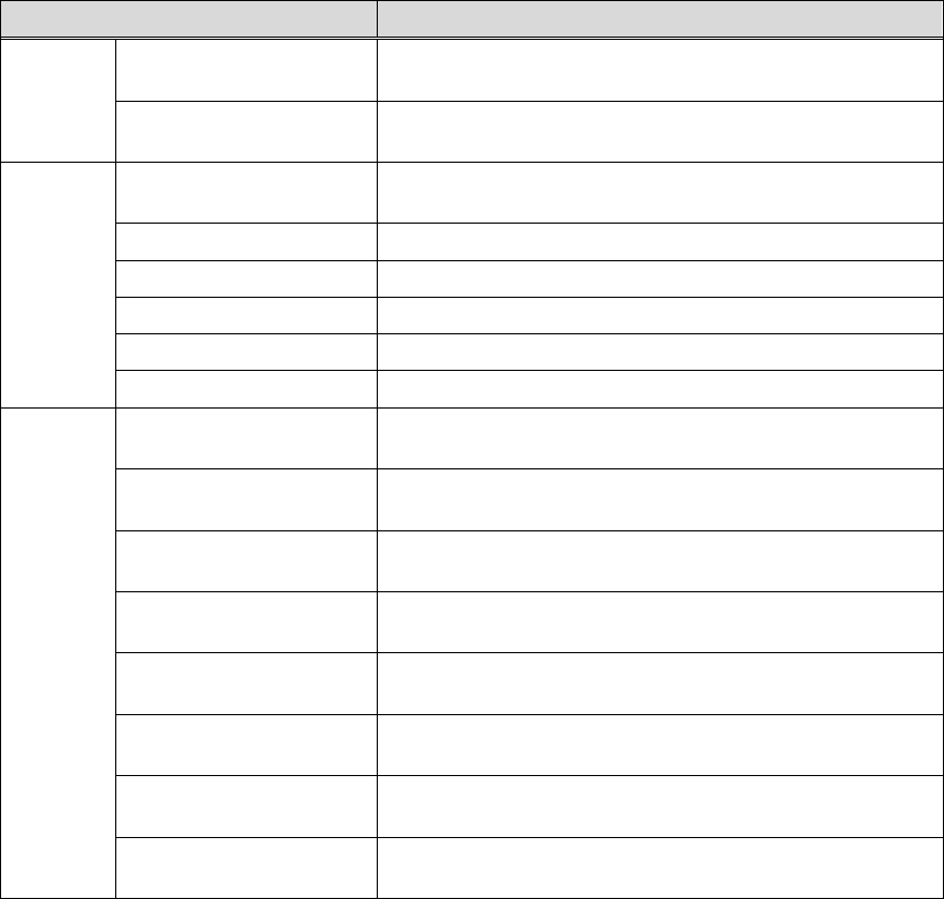
● Fiducial Mark (Pattern matching)
① Select the model mark type and center it in camera’s field of view.
② Acquire the model data with the size of 1.2 times of the mark.
③ Make a comparison between the saved model mark data and the actually-captured mark
image. Match the saved model mark data to the actual one for position correction.
1 2 3
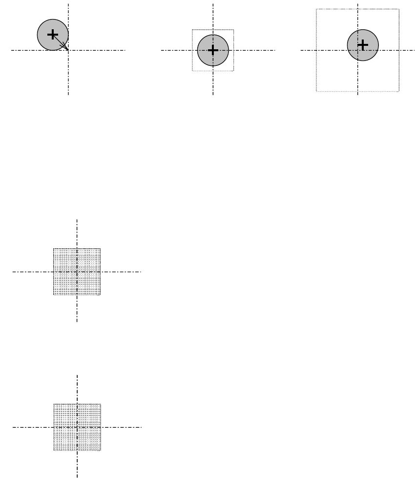
● Fiducial (Center search)
① Select a mark shape. Enter the mark search-area and the mark size.
② The mark center will be calculated from detected mark edges and it will be referred for
fiducial correction.
● Bad Mark (white)
When the average brightness within the specified area is beyond the threshold, OK is issued.
● Bad Mark (black)
When the average brightness within the specified area is under the threshold, OK is issued.