M20_Ope_E - 第167页
Chapter 5 Libraries 5-17 Front-light Settings The front lights for component process is preset fo r gain and offset, as follows. As front lighting increases, gain and offset are raised. Norm ally, use front light 0 or fr…
Chapter 5 Libraries
5-16
5-1-1-5 Illumination Settings
■ Illumination Settings for component recognition cameras
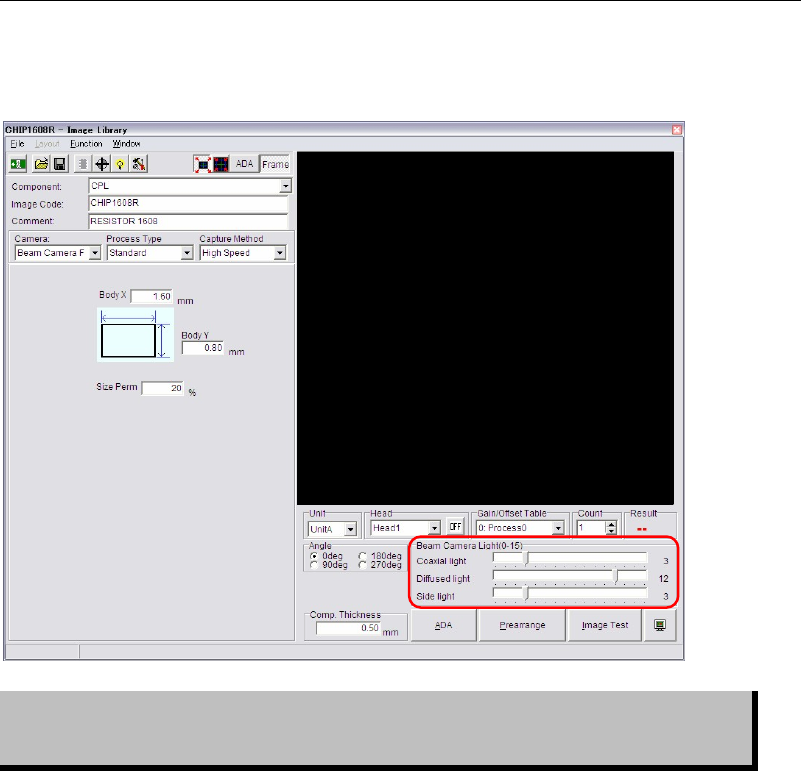
Illumination settings for component recognition cameras can be made in Image Library edit
window.
Setting of illumination data is critical in ensuring correct image processing. View
of the component varies with illumination settings even if the same component is
monitored.
Note: Beam camera (only for the M7) can capture images of the 8 heads at a time.
Illumination settings for components within one cycle should be the same.
If illumination settings are different among them, the beam camera will capture images one by
one with still capture.
Chapter 5 Libraries
5-17
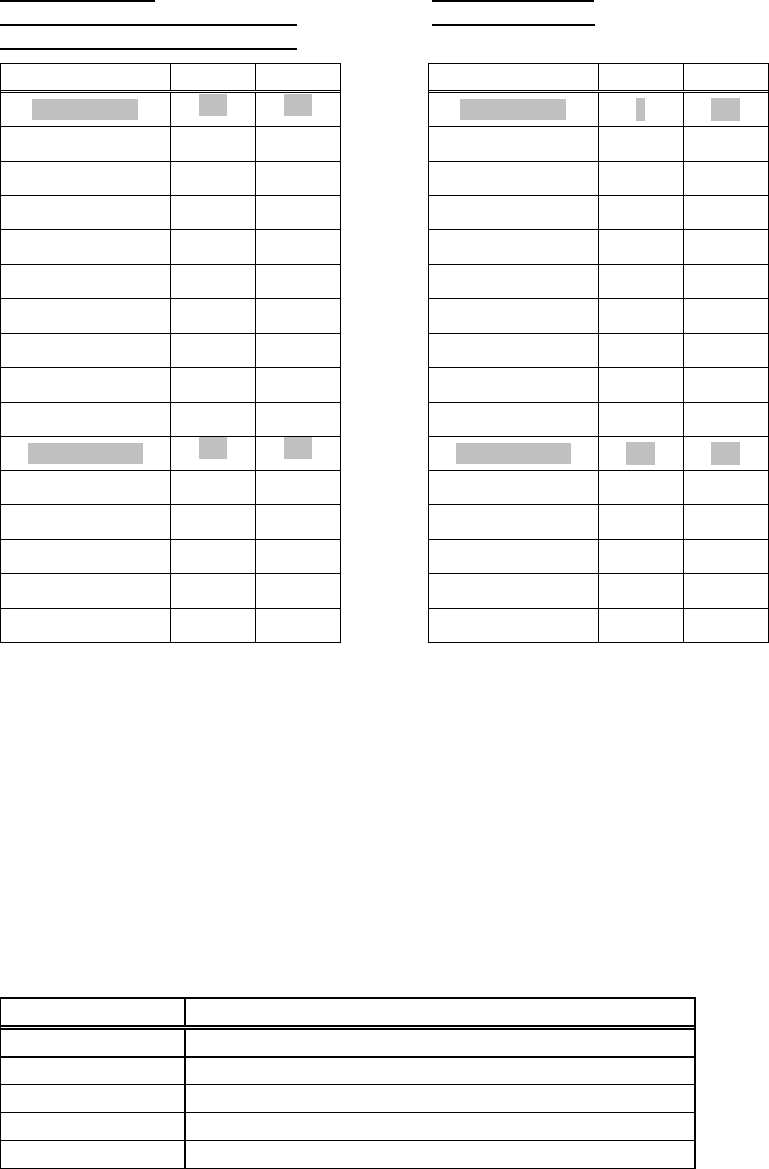
Front-light Settings
The front lights for component process is preset for gain and offset, as follows. As front lighting
increases, gain and offset are raised. Normally, use front light 0 or front light 10.
M6 (Scan Camera)
M6 (Fixed Camera)
M6ex (Scan Camera/Fixed camera)
M7 (Beam Camera)
M6ez (Scan Camera/Fixed camera)
Gain Offset Gain Offset
Front Light 0
110 150
Front Light 0
0 255
Front Light 1
120 150
Front Light 1
10 255
Front Light 2
130 150
Front Light 2
20 255
Front Light 3
140 150
Front Light 3
30 255
Front Light 4
150 150
Front Light 4
40 255
Front Light 5
160 150
Front Light 5
50 255
Front Light 6
170 150
Front Light 6
60 255
Front Light 7
180 150
Front Light 7
70 255
Front Light 8
190 150
Front Light 8
80 255
Front Light 9
200 150
Front Light 9
90 255
Front Light 10
220 120
Front Light 10
150 200
Front Light 11
225 110
Front Light 11
170 180
Front Light 12
230 100
Front Light 12
190 160
Front Light 13
235 90
Front Light 13
210 140
Front Light 14
240 80
Front Light 14
230 120
Front Light 15
245 70
Front Light 15
250 100
Front Light 0
This setting is applied mainly to small components such as chip and transistor. The light of the
scan camera has the brightest center area and peripheral area getting darker, and they can get
sufficient brightness in front light 0.
Front Light 10
This setting is applied to large components such as SOP, SOJ, LCC, PLCC, GSP, connector,
BGA, CSP. The light of the scan camera has the brightest center area and peripheral area
getting darker, and they must get more brightness in front light 10.
Camera Assignment
In most cases you are required to select a camera, the suitable camera has been selected as
default.
Camera Task
Main teach camera Fiducial sensing, bad mark sensing, teach, nozzle ID sensing
Aux. teach camera Teach
Fixed camera 1, 2, 3 Component alignment
Scan camera Component alignment, nozzle presence check
Beam camera Component alignment, nozzle presence check
Scan Camera Illumination Configuration (M6/M6ex)
The light system of the scan camera is available in a main light system (direct light), sub light
system (diffused light), and extra system (slit light). Increased main light enhances regular
reflection. As excessive main light allows the tip of the nozzle and flange to be viewed,
resulting in image processing error, set main lighting in the range of 0 to 3. If using 4 or more,
make sure that the tip of the nozzle and flange are not taken. For the sub light, you can use all
the values (0 to 15).
Chapter 5 Libraries
5-18
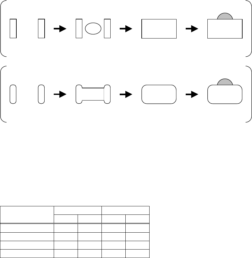
Scan Camera Illumination for Chip Components (M6/M6ex/M6ez)
Determine the light value at which the nozzle is not captured. Set the value so that the entire
component gets even brightness. Use the front light of 0.
Lighting Method
Chip resistor view with only main light increased.
Only electrodes are
viewed.
Center of the body is
viewed.
The
entire
component is
viewed.
The nozzle is
viewed.
Chip capacitor view with only main light increased.
Only electrodes are
viewed.
Center of the body is
viewed.
The
entire
component is
viewed.
The nozzle is
viewed.
Adjust only the main light until the entire component gets even brightness. Make the half of the
value actual main light value. As even brightness for standard chip components is achieved at
the main light of 6, use the main light of 3. After the main light has been set, adjust the sub light
and measure the component using image test feature. Determine the sub light for correct size.
Set the sub light of about 10 for standard chip resistors. Use about 12 for standard chip
capacitors.
● Scan Camera Illumination for Resistors and Capacitors
Component Size
Resistor Capacitor
Main Sub Main
Sub
1005 3 10 3 12
1608 3 10 3 12
2125 3 10 3 12
3216 3 10 3 12