M20_Ope_E - 第171页
Chapter 5 Libraries 5-21 Example: When a transistor is fed in the arrow dire ction in the feeder set on the front bank, Feed directi on the picked transistor, viewed from a fixed camera or a beam camera, is seen as shown…

Chapter 5 Libraries
5-20
■ Fixed Camera Illumination (M6)
Three kinds of illumination are available for fixed cameras: “Coaxial”, “Diffused” and “Side”.
“Coaxial” acts as direct light, “Diffused” as diffused light and “Side” as sideways slit light.
Normally, these three illuminations are used together to provide diffused light consisting of
light from various directions. For BGA and CSP components, only “Side” must be used.
■ Fixed Camera Illumination (M6ex/M6ez)
Three kinds of illumination are available for fixed cameras: “In”, “Out” and “Side”. “In” acts as
direct light, “Out” as diffused light and “Side” as sideways slit light.
Normally, these three illuminations are used together to provide diffused light consisting of
light from various directions. For BGA and CSP components, only “Side” must be used.
■ Beam Camera Illumination (M7)
Three kinds of illumination are available for beam cameras: “Coaxial”, “Diffused” and “Side”.
“Coaxial” acts as direct light, “Diffused” acts as diffused light, and “Side” acts as sideways slit
light.
For standard components, use “Diffused” as major light and “Coaxial” as subsidiary light.
Normally, use “Coaxial” and “Diffused”. (recommended to set the same value for both.)
For components with J-leads(SOJ and PLCC etc.), these three illuminations are used together to
provide diffused light consisting of light from various directions. For BGA and CSP
components, only “Side” must be used.
● Beam camera illumination settings for registers and capacitors
E.g.)
Component Size
Resistor Capacitor
Coaxial Diffused
1005 6 10
1608 6 10
2125 6 10
3126 6 10
■ Teach Camera Illumination
Two kinds of illumination are available for teach cameras: “In” and “Out”. “In” acts as direct
light and “Out” dose as diagonal diffused light.
● “Gain” and “Offset” for Fiducial mark and Bad mark
An original image outputted by a camera is processed for better and stable one by adjusting
“Gain” and “Offset” value.
Increasing “Gain” value clears the contrast and increasing “Offset” value intensifies the entire
brightness.
Specify the value in “Gain”/”Offset” for fiducial mark and bad mark. Increase “Gain” value to
clear the contrast and decrease the “Offset” value for fine adjustments.
Scanning Direction
Teach cameras look downward. Scan cameras, fixed cameras and beam cameras look upward.
The operator, when watching components and a board in the machine, looks downward. The
operator and the teach camera face in the same direction, however scan cameras, fixed cameras
and beam cameras in the opposite direction to provide a mirror image.
Chapter 5 Libraries
5-21
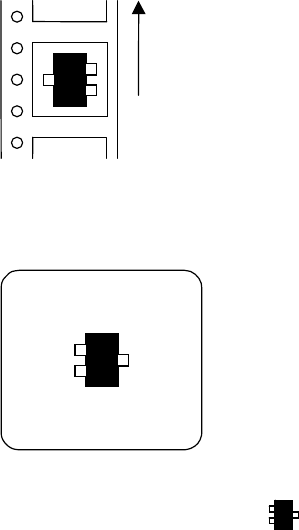
Example:
When a transistor is fed in the arrow direction in the feeder set on the front bank,
Feed direction
the picked transistor, viewed from a fixed camera or a beam camera, is seen as shown on the
monitor as the figure blow.
Select "Transistor-Right" mode ( ) in the image library.
Chapter 5 Libraries
5-22
5-1-2 Image Data Creation Support Tool
Since some image data are already registered in the master library, necessary image data can be
copied from it to the user library and used.
Four tools are available to create new image data. They include the illumination adjustment,
prearrange, ADA (Automatic Data Acquisition) and image test tools. Use of the illumination
adjustment tool makes illumination setting for components easier. Use of the prearrange tool
causes the mounter to pickup a component with a nozzle and hold it over the camera.
Use of the ADA tool enables easy image creation. The image test tool checks whether the
created data can be used for actual placement operation. The image test tool can also be used
for mark data.
The ADA and image test tools have the following restrictions depending on the processing
target.
○: Can be executed. ×: Cannot be executed or execution is not necessary.
Processing target ADA Image test
Chip, Electrolytic capacitor, Transistor,
Power transisitor
○ ○
SOP,SOJ,QFP,PLCC,LCC
○ ○
BGA/CSP
○ ○
Connector
× ○
Fiducial mark
× ○
Bad mark
× ○
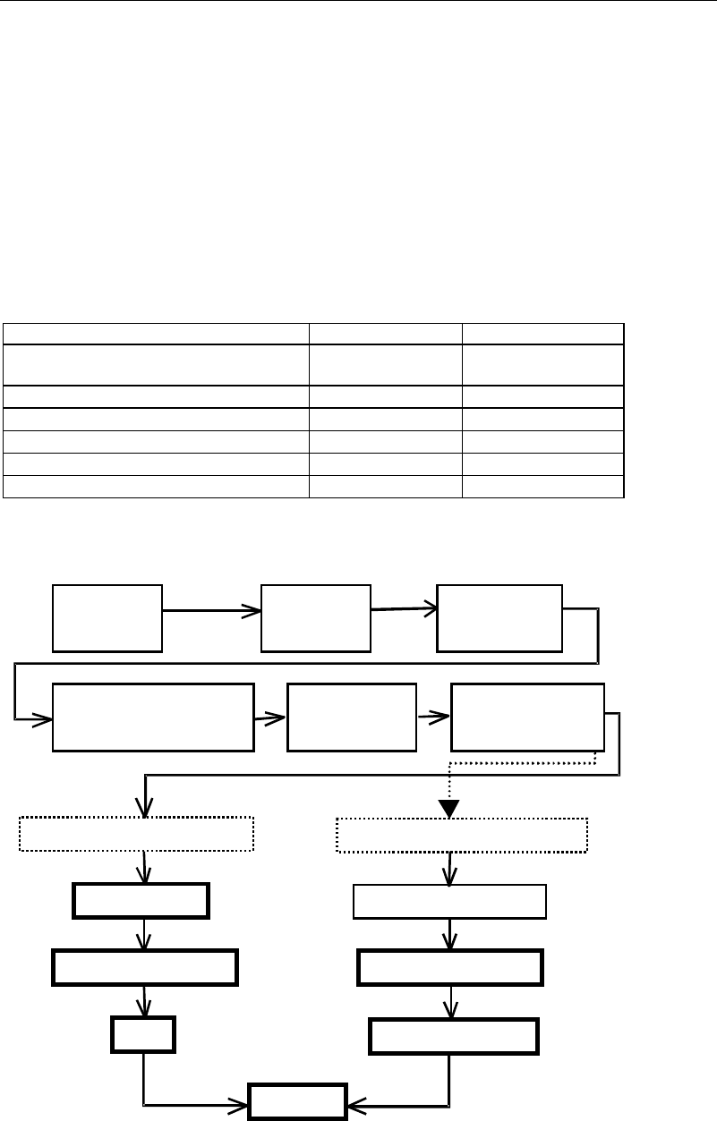
An outline of the procedure for creating image data using the above support tools is given
below.
A
ttach nozzles
to ANC.
A
ttach nozzles
to heads.
Select an image
library.
Select the component type in
the image code list window.
Image data edit
window
opens.
Enter dimensions.
Components supported by ADA
Components not supported by ADA
Prearrange
Enter dimensions.
Illumination setting
Illumination setting
ADA
Image test
Specify the image code
and processing method.