M20_Ope_E - 第172页
Chapter 5 Libraries 5-22 5-1-2 Image Data Creation Support Tool Since some image data are already registered in the master library, necessary image data can be copied from it to the user library and used. Four tools are …
Chapter 5 Libraries
5-21
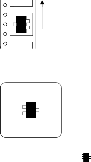
Example:
When a transistor is fed in the arrow direction in the feeder set on the front bank,
Feed direction
the picked transistor, viewed from a fixed camera or a beam camera, is seen as shown on the
monitor as the figure blow.
Select "Transistor-Right" mode ( ) in the image library.
Chapter 5 Libraries
5-22
5-1-2 Image Data Creation Support Tool
Since some image data are already registered in the master library, necessary image data can be
copied from it to the user library and used.
Four tools are available to create new image data. They include the illumination adjustment,
prearrange, ADA (Automatic Data Acquisition) and image test tools. Use of the illumination
adjustment tool makes illumination setting for components easier. Use of the prearrange tool
causes the mounter to pickup a component with a nozzle and hold it over the camera.
Use of the ADA tool enables easy image creation. The image test tool checks whether the
created data can be used for actual placement operation. The image test tool can also be used
for mark data.
The ADA and image test tools have the following restrictions depending on the processing
target.
○: Can be executed. ×: Cannot be executed or execution is not necessary.
Processing target ADA Image test
Chip, Electrolytic capacitor, Transistor,
Power transisitor
○ ○
SOP,SOJ,QFP,PLCC,LCC
○ ○
BGA/CSP
○ ○
Connector
× ○
Fiducial mark
× ○
Bad mark
× ○
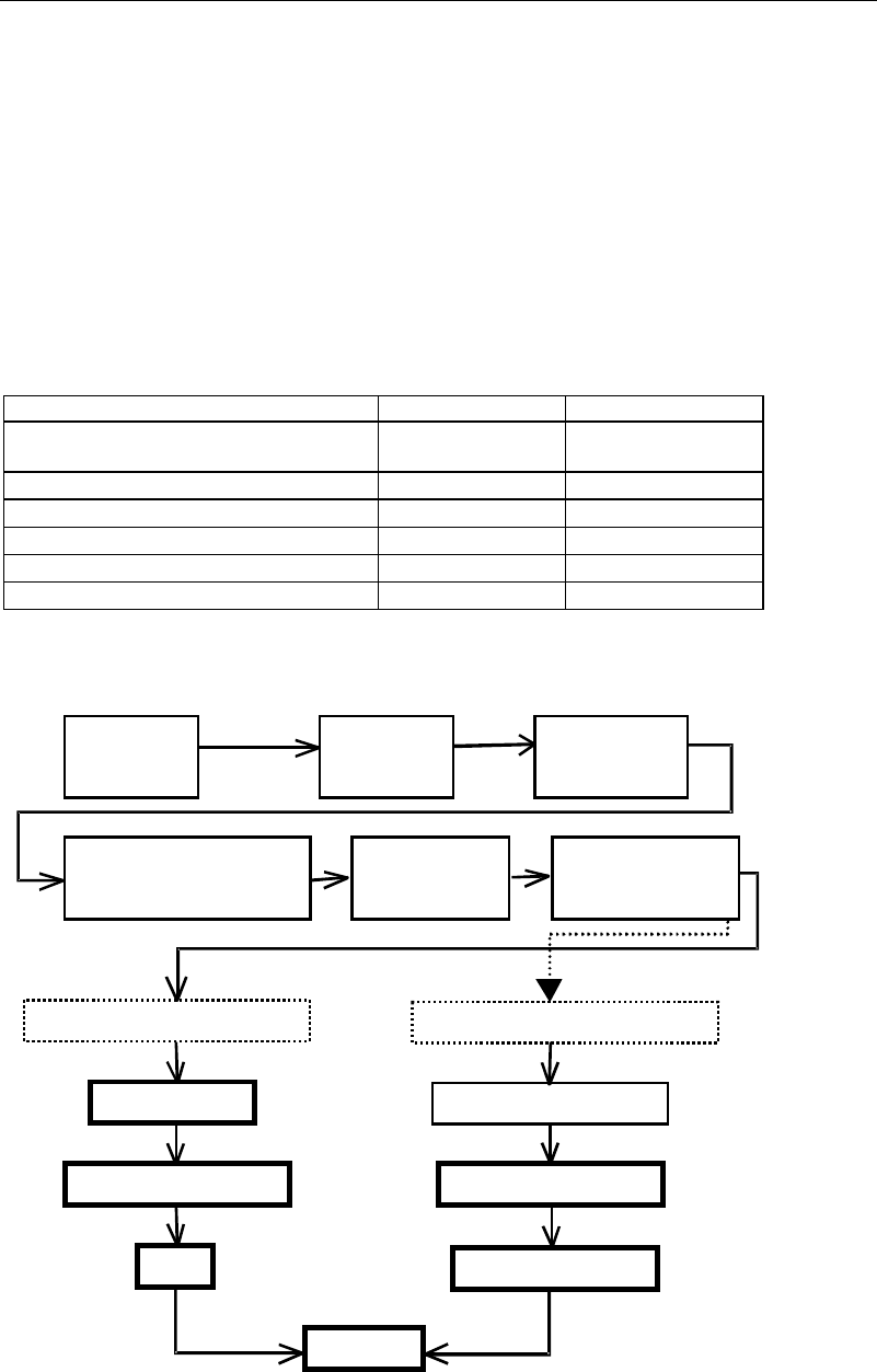
An outline of the procedure for creating image data using the above support tools is given
below.
A
ttach nozzles
to ANC.
A
ttach nozzles
to heads.
Select an image
library.
Select the component type in
the image code list window.
Image data edit
window
opens.
Enter dimensions.
Components supported by ADA
Components not supported by ADA
Prearrange
Enter dimensions.
Illumination setting
Illumination setting
ADA
Image test
Specify the image code
and processing method.
Chapter 5 Libraries
5-23
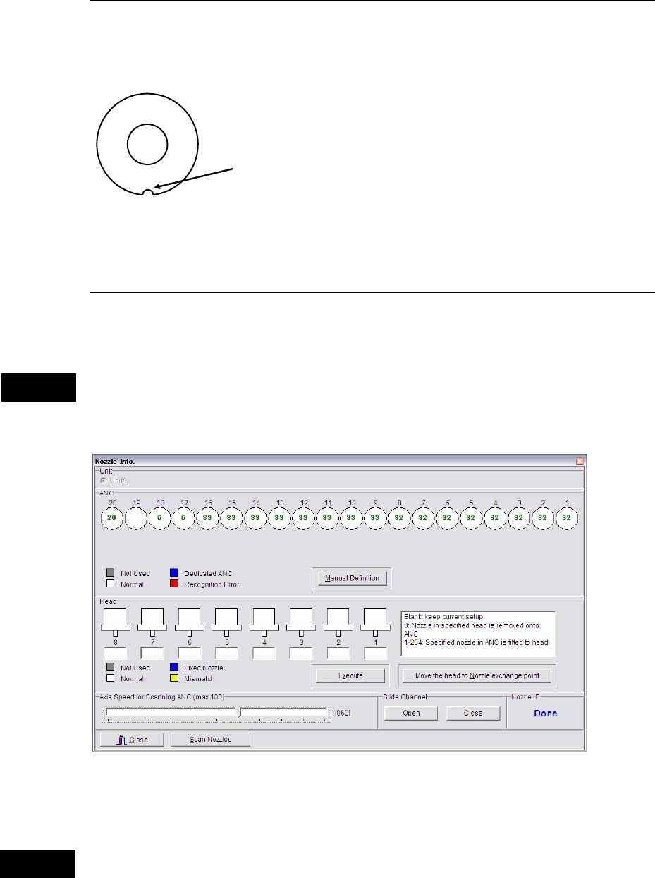
5-1-2-1 Setting Nozzles to ANC
Set nozzles to use to available ANC stations. Open the ANC shutter in advance, Nozzle
Info.>Slide Channel>Open. When setting them, fit the nozzle cutoff to the positioning pin in
the ANC station and insert the nozzle vertically.
Cutoff
Nozzle Top view
Note: When the head assembly or XY shafts locate above the ANC station, make enough space to
work. Click the <Move the head to Nozzle exchange point> button.
5-1-2-2 Setting Nozzles to Heads
Menu: Manual>NozzleInfo.
This system is capable of automatic nozzle setting to a head.
Do not manually attach a nozzle to a head. If a nozzle is not attached properly, it can hit other
parts of the machine to result in head damage.
This menu allows you to see which nozzles are on the heads and in ANC.
* The number of units and heads
varies according to machine
models and types.
ANC operation allows a head to move. When using this menu, do not stick head, hands,
or other parts of the body inside the mounter. Serious injury can result. Also make sure
non-operators are a safe distance from the machine.
Caution
Warning