M20_Ope_E - 第184页
Chapter 5 Libraries 5-34 ④ Exit the Prearrange window and go ba ck to the Image data edit window. ⑤ Click the <Fra me> button at the upper part of the window. The component frame performed b y the ADA is able to ap…
Chapter 5 Libraries
5-33
M7
Executing Image Test
Action: To execute Image test, select the Image data edit window.
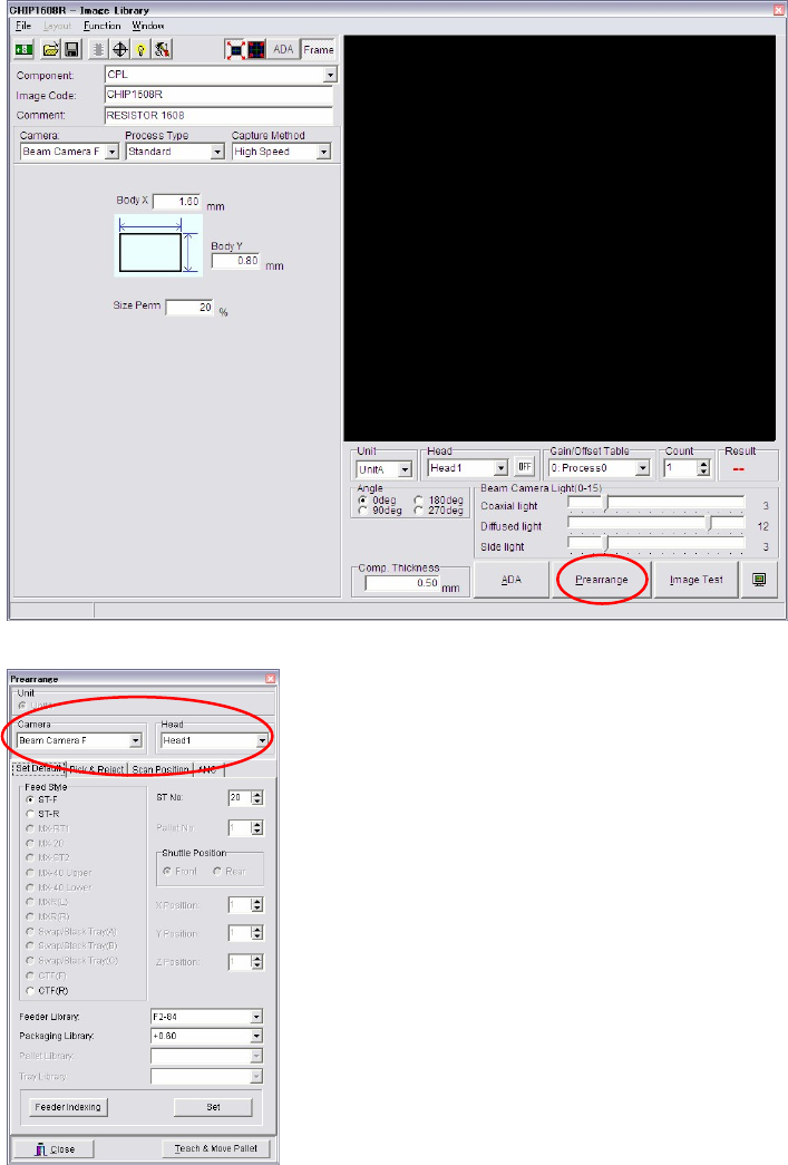
① In the Image data edit window, type the image code, and comment. Select Camera, Unit
and Head.
② Make sure [Comp. Thickness] value is correct. If not, type the proper value.
③ Attach a component to a nozzle through Prearrange.
Note: Make sure Unit, Camera and Head are selected properly.
Chapter 5 Libraries
5-34
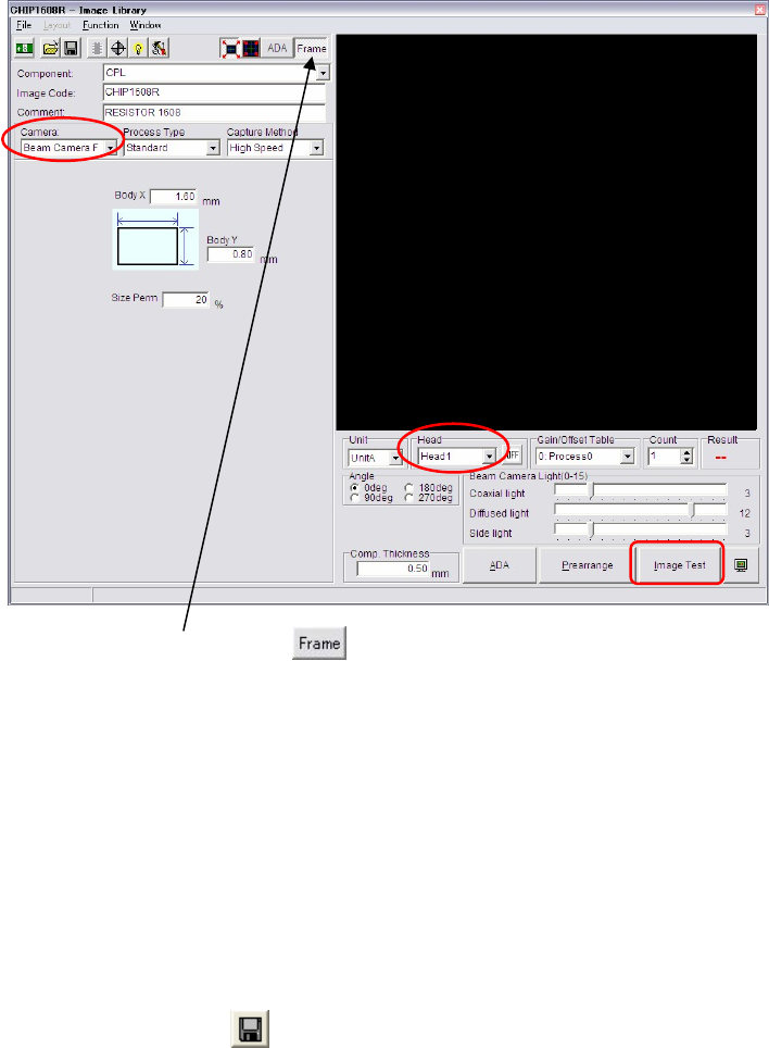
④ Exit the Prearrange window and go back to the Image data edit window.
⑤ Click the <Frame> button at the upper part of the window.
The component frame performed by the ADA is able to appear in this VCS monitor.
⑥ Check to see that [Camera], [Unit] and [Head] are correctly selected.
Click <Image Test> button to execute Image Test.
⑦ The message “Execute?” appears. Click <OK> button. Then the message “Move the head to
camera's scan position?” appears. Click <Yes> button.
⑧ The result of image test is displayed enlarged initially. To enlarge and reduce the image,
scroll the mouse wheel. To move the image within the VCS monitor, drag the mouse.
Note: Enlarge the image and check the result of Image Test precisely.
⑨ When the image test ends in success, [OK] is displayed in the Result box. If the image test
fails, [NG] is displayed. In this case, follow the displayed message.
⑩ Remove or reject the component from the nozzle through Prearrange.
⑪ Click File>Save or button to register the data.
Note: 8 heads are subjected to vision processing at one time. Set the same illumination values for
components within a same cycle.
When illumination set values for components within one cycle vary, or you need to enter
unique illumination value for each component, the components will be still captured by each
group of components with the same illumination values.
Chapter 5 Libraries
5-35
Window: (Display of the screen)
Expect Size: Component size typed in the Image Library edit window.
Actual Size: Actual measured component size
DX (Difference X): X offset from the center of the nozzle
DY (Difference Y): Y offset from the center of the nozzle
DA (Difference A): Component tilt towards the X/Y axis
Permission: Allowable value of the size typed in the Image Library edit
window.
Mark
Action:
① In the Fiducial/BadMark Data edit window, click <Image Test> button.
② When the image test ends in success, [OK] is displayed in the Result box. If the image test
fails, [NG] is displayed. In this case, follow the displayed message.
③ Save the data.
Window: (Display of the screen)
Accept: Match. threshold entered to the Image Library edit window.
Score: Score obtained in the fiducial matching process.
DX (Difference X): X offset from the fiducial coordinates.
DY (Difference Y): Y offset from the fiducial coordinates.
Mode: Bad mark color. 0: White, 1: Black
Bright: White/black threshold of the bad mark.
Measure: Measured brightness of the bad mark.