M20_Ope_E - 第19页
Chapter 1 General 1-1 Chapter 1 General Parts identification System startup and shutdown Menu Views Movable Range of Head Assembly Adjusting Rear clamp Adjust Pick-up Pin Height PCB Clamp conveyor (option)

Contents
14-4-2
Auxiliary Explanation for Relocatable Function ................................................................................................ 14-27
14-4-3 Command Barcodes ............................................................................................................................................... 14-29
Chapter 15 DATA .................................................................................................................... 15-1
15-1 MMI Messages........................................................................................................................................ 15-6
Chapter 17 Multi Conveyor .................................................................................................... 17-1
Multi Conveyor Outline .......................................................................................................................................................... 17-2
Parameter settings .................................................................................................................................................................... 17-2
PCB Data ................................................................................................................................................................................. 17-4
Manual Operation .................................................................................................................................................................... 17-5
Chapter 1 General
1-1
Chapter 1
General
Parts identification
System startup and shutdown
Menu Views
Movable Range of Head Assembly
Adjusting Rear clamp
Adjust Pick-up Pin Height
PCB Clamp conveyor (option)
Chapter 1 General
1-2
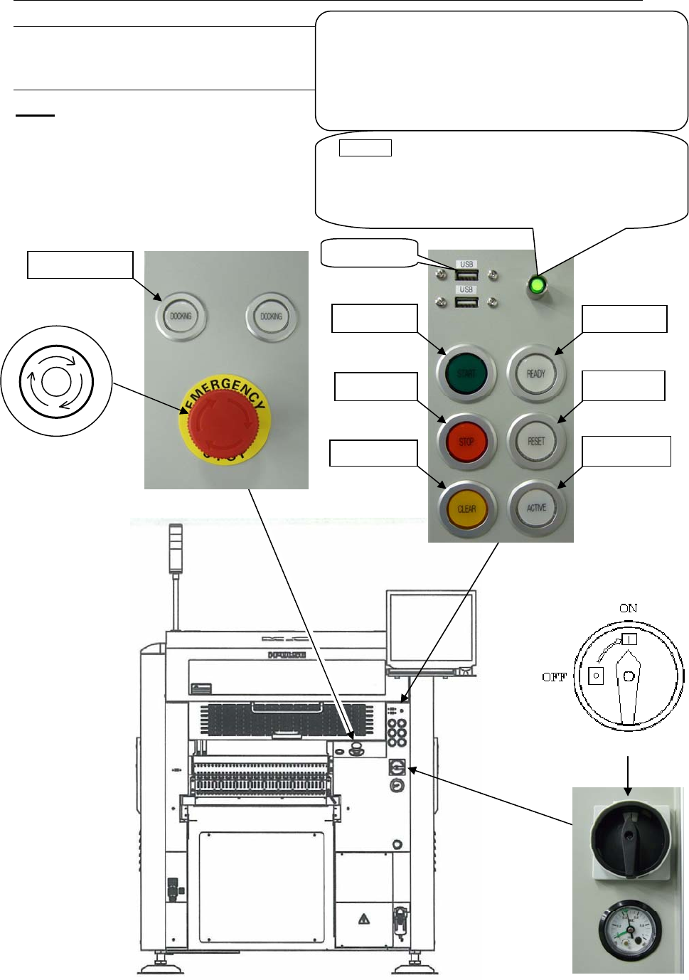
1-1 Parts Identification
1-1-1 Controls of the Mounter
M10
Front View
Note: Configuration of the control switches varies depending on each machine configuration.
3. READY
5. START
4. RESET
6. STOP
8. ACTIVE
7. CLEAR
USB
p
ort
POWER (Green lamp)
This lamp lights up green when the machine computer
is turned on. Normally this button is not used. Use it
only when the machine computer does not start up
even if the main switch button is pressed.
UPS option
The UPS backs up the power supply of the machine
computer, LCD, and servo motors for controller when
electric failure occurs but does not backs up the power
supply of servo motors for driving.
To shut down the UPS, hold down this button over five
seconds.
9. DOCKING
2. Emergency Stop switch
P
O
T
S
E
Y
C
N
E
G
R
E
M
1. Main Switch