M20_Ope_E - 第192页
Chapter 5 Libraries 5-42 Placement Speed (XY 、 Z 、θ ) Placement speed 1 (minimum speed) to 100 (maximum speed) (Unit: %) See the chart below. Placement acceleration 1 (minimum sp eed) to 100 (maximum speed) (Unit: %) Pic…
Chapter 5 Libraries
5-41
Camera
Distance from camera
Thickness
Comp Pickup Surface Hei
g
ht
Z offset for vision process
Thickness
Camera
Distance from camera
Comp Pickup Surface Height
5-1-3-4 Advanced Settings
Menu: Component Library>Tool>AdvancedSetting
You can define miscellaneous settings related to the pickup, placement, and vision process of
the component. Usually default settings will do. But when there is a need to change the setting,
click the line of the component and select this menu.
Window:
Retry:
Vision Process Retry: The number of retries if vision process error occurs.
Select a value from 0 to 9.
Pickup Retry: The number of retries if pick up error occurs.
Select a value from 0 to 9.
Choke/Feeder Retry: The number of retries if nozzle clogging or feeder trouble occurs.
Select a value from 0 to 9.
Vision Process Time:
This setting is used for the calculation of Simple Placement Optimization, The parameter
cannot be edited.
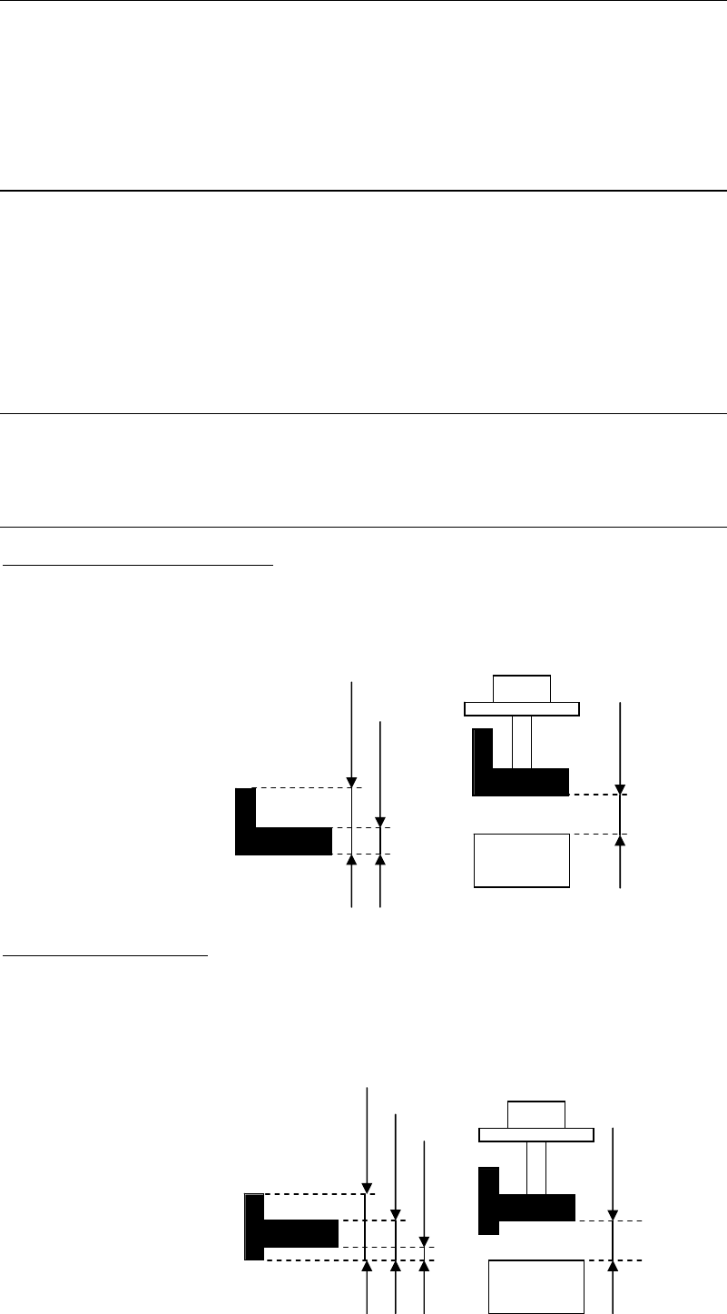
Detailed Thickness:
Component Pickup Surface Height:
Specify the length from the bottom to the pickup surface. No need to specify when it is the
same as the component thickness.
Z offset for vision process:
Specify the offset value for vision process if the target surface for vision process is not at the
bottom of the component.
Chapter 5 Libraries
5-42
Placement Speed (XY、Z、θ)
Placement speed 1 (minimum speed) to 100 (maximum speed) (Unit: %)
See the chart below.
Placement acceleration 1 (minimum speed) to 100 (maximum speed) (Unit: %)
Pickup Speed (Z)
Pickup speed 1 (minimum speed) to 100 (maximum speed) (Unit: %)
See the chart below.
Pickup acceleration 1 (minimum speed) to 100 (maximum speed) (Unit: %)
Placement Timing
Head suction off ← Head down complete at PCB (Positive Value: OFF before, Negative Value:
Off after)
Vacuum Brkr on command at PCB → Vacuum Brkr off command
X,Y-axis motors stop at PCB → Head down command
Head down complete signal at PCB → Head up command
Pickup timing
Head down complete signal at feeder → Head up command
X,Y-axis motors stop at feeder → Head down command
Others
Vacuum Check > Enter pickup threshold [mmHg]
If you want to set the pickup vacuum threshold value for each component, make setting for this
item. (Unit: mmHg) The default is “0”. (If “0” is set, the pickup vacuum threshold value for the
nozzle that picks up this component will be used.)
Default > Feeder/Pallet
If the feeder/pallet to be used for this component has been specified, it will be entered in
[Feeder/Pallet] automatically when the component code is entered in the pickup data or when
<Copy Code> button is clicked.
Default > Packaging/Tray
If the component feeder/tray to be used for this component has been specified, it will be
entered in [Packaging/Tray] automatically when pickup data is created.
Component Remain Count Management > Initial Supply Count
Enter an initial supply count value for this component. (Unit: pcs.)
Normally, enter the number of components in the packaging state directly.
See Chapter 9_ Running a job > ● Component Remain Count Management> Advanced Setting
for Component Library
Pl
ace
m
e
n
t
speed
Pickup point
Pl
ace
m
e
n
t
po
in
t
Pickup speed
Z

Chapter 5 Libraries
5-43
Component Remain Count Management > Shortage Alarm
Enter a shortage Alarm value for this component. (Unit: pcs.)
See Chapter 9_ Running a job > ● Component Remain Count Management> Advanced Setting
for Component Library
Limit of Correction > X/Y/T
Specify the upper limit of correction for image processing. An image processing error will
occur if this setting is exceeded by the correction result. If this is set to “0”, the setting made for
[Pass Score for Vision Process Result (XY, T)] (User Parameter >Parameters) will be referred to.
Component Reject/Reuse Timing > VacmBrkr on comnd at Comp. Reject/Reuse -> VacmBrkr
off comnd
(When 0 is specified, the value of “Placement Timing” will be applied.)
A period of the vacuum break time when this component is rejected or reused is set. When “0”
is specified, Advanced Setting>Placement Timing “Vacuum Brkr on command at PCB →
Vacuum Brkr off command” for this component will apply.
Component Reject/Reuse Timing > Head down complete signal at Comp. Reject/Reuse ->
Head up comnd
(When 0 is specified, the value of User Parameter will be applied.)
A period of the head down time when this component is rejected or reused is set.
When “0” is specified, System>User Parameter>Timings>Component Reject, Z Lowest End ->
Head Up/Component Reuse, Z Lowest End -> Head Up will apply.
Component Reject/Reuse Timing > [Batch Setting] button
The component reject/reuse timing for this component will affect all components.
Force Control (Placement)
A load when this component is placed is set. (Unit: N)
This force control does not apply to a component that uses the nozzle P050 to P053.
(A load when this component is placed cannot be set.)
Normally, set the default value.
Force control (Pickup)
A load when this component is picked up is set. (Unit: N)
This force control does not apply to a component that uses the nozzle P050 to P053.
(A load when this component is picked up cannot be set.)
Normally, set the default value.
Pickup Setting
MSF Feeding Time Offset
When the MSF-1 multi-stick feeder is used to supply the component, a feeding time offset is set
for each component. (Unit: sec)
"MSF-1" vibration time = "MSF-1" feeding time + MSF feeding time offset.
For details, see the manual for MSF-1 multi-stick feeder.