M20_Ope_E - 第199页
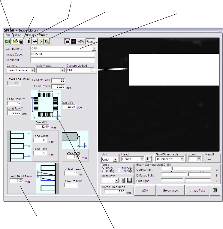
Chapter 5 Libraries 5-49 The above shows a typical image data editor window. Window: File>Open: Opens the list of existing image data of the selected component type (e.g. QFP for the above screen). Select a file and c…
Chapter 5 Libraries
5-48
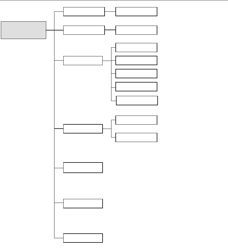
5-1-5-2 Image Data Configurations
Component Image Data
Pre-alignment
Multiple-view Process
Camera
Scan Camera
Fixed Camera 3
Fixed Camera 2
Fixed Camera 1
Size Data
Specify missing leaded/balled positions
for ICs/BGAs.
This setting is crucial in determining
how well the target is captured.
Missing lead/Ball Data
Illuminator Settings
Permissions
Process Options
Component Name
Comment
* Not used.
Advanced Settings
Specify judgment condition etc. when using
the component orientation check function.
Beam Camera
Chapter 5 Libraries
5-49
The above shows a typical image data editor window.
Window:
File>Open: Opens the list of existing image data of the selected component type
(e.g. QFP for the above screen). Select a file and click <Open>
button. To delete a file, select a file and click <Delete> button.
File>Save As…: Saves the current file with a name (image code) and comment.
Comment is not necessarily required.
File>Save Overwrites the current file.
File>Exit: Closes the Open File dialog box.
Component: Component type selected in the previous dialog box. When there
are additional options to select, click <Mode> button to make a
choice.
Image Code: When creating new image data, enter a desired code. When editing
an existing data, its code is displayed. Image code serves to link the
image library and component library.
* Up to 38 characters can be entered.
Comment: Any appropriate comment
* Up to 40 characters can be entered.
For information about Camera, Multi Views, Pre-align, and other settings, see the following
section.
Image box:
Shows an explanatory graphic for the
selected component type. The direction of
the graphic corresponds to the direction of
the monitored image.
Clicking this button opens the missing lead/ball window. In the
case of BGA/CSP, the random ball arran
g
ement is set.
Click this button to open
an existing file.
Click this button to open the
Advanced Setting Window.
Click this button to save
the current file.
If component types have been grouped, click
this to select another component type.
Component data setting area
Select whether the On-the-fly capture with
Fixed / Beam camera is used or not, and set
the speed.
(On M6ex, still capture is only available.)
Chapter 5 Libraries
5-50
5-1-5-3 Image Library Advanced Setting
Menu: ImageLibrary>AdvancedSetting>ComponentOrientationCheck
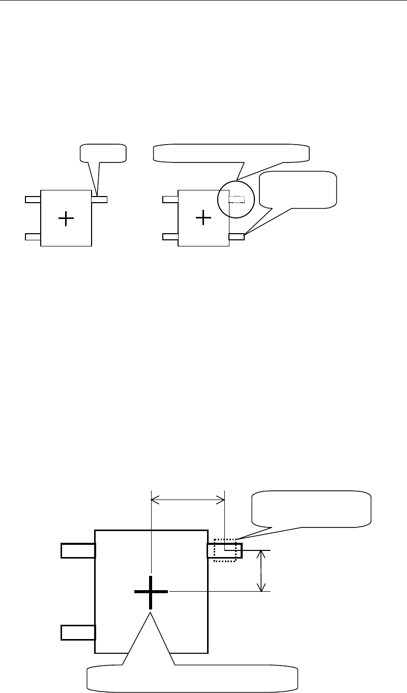
This function identifies the orientation of the picked-up component. For some component
types, this function can also be used to identify the front/rear of the component.
Assuming that the illustration on the left shows the image of a component when it is picked up
in correct orientation. However, if the component is picked up in reversed orientation and its
image is captured (see the illustration on the right), lead A will not be shown at the position
where it should be recognized, but shown in a position where it should not be.
Image captured when
the component is in
correct orientation
Lead
A
Image captured when
the component is in
reverse orientation
Not shown in the original position
Recognized at
another position
Like the above example, if the component has a “judgment feature” that can show clear
difference in the image between when the component is in correct orientation and when it is in
reverse orientation, front/rear judgment can be made by setting the “Component Orientation
Check” condition.
●Setting example for front/rear judgment
Condition setting to perform component orientation check (front/rear check) for the
component shown below is explained on the next page.
Center of component when recognized
Distance Y
Distance X
Feature search area
(Specify the size)